
Demystifying UART, SPI, and I2C: Communication Between Chips
In both VLSI design and embedded systems, no chip operates in isolation. Whether it’s a microcontroller interfacing with sensors, a processor communicating with memory modules, or multiple peripherals synchronizing data, inter-chip communication is fundamental to building reliable and scalable hardware systems.
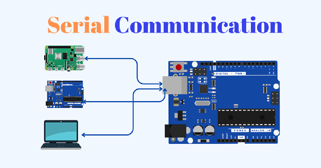
As systems grow in complexity, so does the demand for structured, efficient, and purpose-fit communication protocols. Direct parallel connections are rarely feasible due to board space, pin limitations, and synchronization challenges. Instead, designers turn to well-established serial communication standards that enable devices to exchange data with minimal wiring and clear electrical and timing definitions.
Three of the most widely used protocols for such tasks are:
- UART (Universal Asynchronous Receiver/Transmitter)
- SPI (Serial Peripheral Interface)
- I²C (Inter-Integrated Circuit)
Each of these protocols is optimized for different trade-offs—speed, simplicity, scalability, and wiring complexity—making them suited for specific use cases in VLSI blocks, SoCs, microcontroller boards, and embedded devices.
Brief Overview of the Protocols
UART – Universal Asynchronous Receiver/Transmitter
UART is a point-to-point, asynchronous serial protocol used to transmit data without needing a clock line. Instead, both devices agree on a predefined baud rate. Communication occurs over two lines: TX (transmit) and RX (receive).
It’s widely used for debugging, console communication, and bootloaders, especially when simplicity and human-readable interfaces (e.g., serial terminals) are priorities. Since it doesn’t support addressing or multiple devices, it’s typically used for direct, one-to-one communication.
SPI – Serial Peripheral Interface
SPI is a synchronous, full-duplex protocol that uses four wires in its standard configuration: MOSI, MISO, SCLK, and CS (Chip Select). Data is clocked simultaneously in both directions, allowing high-speed transfers.
SPI is ideal when speed and performance matter—common in display drivers, flash memory, ADCs/DACs, and high-throughput sensors. It supports multiple slaves but requires a separate chip-select line for each, which can limit scalability.
I²C – Inter-Integrated Circuit
I²C is a synchronous, half-duplex protocol that operates on just two wires: SDA (data) and SCL (clock). It allows for multi-master and multi-slave communication, where each device has a unique address.
I²C is favored for connecting multiple low-speed peripherals, such as sensors, EEPROMs, and configuration ICs, particularly when board space and wiring simplicity are critical. Its slower speeds and shared bus make it less ideal for high-volume data transfer but excellent for control applications.
Protocol Comparison at a Glance
| Feature | UART | SPI | I²C |
|---|---|---|---|
| Communication Type | Asynchronous, full-duplex | Synchronous, full-duplex | Synchronous, half-duplex |
| Wires Required | 2 (TX, RX) | 4 (MOSI, MISO, SCLK, CS) | 2 (SDA, SCL) |
| Multi-Device Support | No | Yes (via multiple CS lines) | Yes (via addressing) |
| Speed | Moderate (depends on baud rate) | Very High (10s of MHz) | Low to Moderate (up to ~3.4 MHz) |
| Complexity | Low | Medium | Medium-High (due to addressing and arbitration) |
| Best For | Debugging, serial logging | High-speed sensors, memory | Low-speed sensors, config ICs |
| Flow Control | Optional (hardware/software) | Master controlled | Clock stretching by slave |
| Hardware Requirement | UART peripheral | SPI controller | I²C controller with open-drain pins |
Which One Should You Use?
The choice of protocol depends on system constraints:
- Use UART when you need simple, direct communication, especially for console output or single peripheral interfaces.
- Use SPI for high-speed communication with a small number of peripherals that demand fast response or large data transfer volumes.
- Use I²C when you need to connect multiple peripherals with minimal wiring and address-based access, especially in sensor arrays and configuration-heavy devices.
In the sections that follow, we’ll explore each protocol in technical depth—from electrical characteristics and signal timing to addressing, framing, and typical use cases. The goal is to not just describe them, but to understand why each behaves the way it does, and how to integrate them correctly into real-world systems.
Stay tuned for the deep dives on UART, SPI, and I²C.
Related Posts
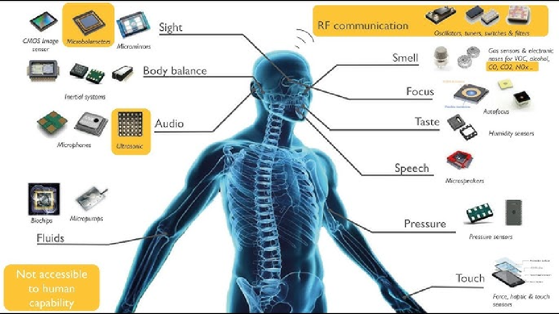
Sensors in Robotics: How Ultrasonic, LiDAR, and IMU Work
Sensors are to robots what eyes, ears, and skin are to humans—but with far fewer limits. While we rely on just five senses, robots can be equipped with many more, sensing distances, movement, vibrations, orientation, light intensity, and even chemical properties. These sensors form the bridge between the digital intelligence of a robot and the physical world it operates in.
Read more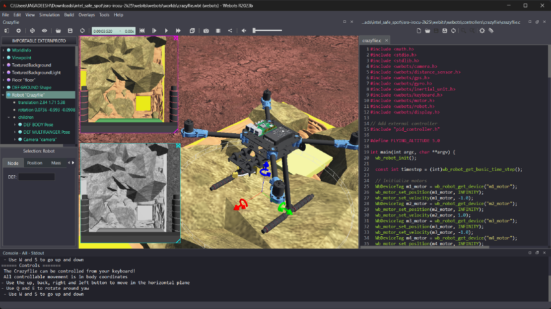
Debugging a Robot In Simulation Before You Burn Wires
Hardware does not come with an undo button. Once you power it on, mistakes—from reversed wiring to faulty code—can result in costly damage. Motors may overheat, printed circuit boards (PCBs) can be fried, and sensors may break. These issues turn exciting projects into frustrating repair sessions. The autonomous drone shown above, designed for GNSS-denied environments in webots as part of the ISRO Robotics Challenge, is a perfect example—where careful planning, testing, and hardware safety were critical at every step
Read more
Computer Vision vs. Sensor Fusion: Who Wins the Self-Driving Car Race?
Tesla’s bold claim that “humans drive with eyes and a brain, so our cars will too” sparked one of the most polarizing debates in autonomous vehicle (AV) technology: Can vision-only systems truly compete with—or even outperform—multi-sensor fusion architectures?
Read more