
I²C: Fundamentals and Practical Aspects of Inter-Integrated Circuit Communication
I²C is a synchronous, half-duplex, multi-master, multi-slave serial communication protocol developed by Philips (now NXP) in the 1980s. It was designed for on-board communication between integrated circuits, especially in systems with multiple low-speed peripherals controlled by a microcontroller.
It prioritizes simplicity and scalability over speed, making it ideal for communication over short distances with minimal wiring.
Fundamental Signal Lines
I²C uses only two bi-directional lines:
- SDA (Serial Data Line) – Carries the data.
- SCL (Serial Clock Line) – Carries the clock signal generated by the master.
Both lines are open-drain (or open-collector), meaning devices can pull the line low but cannot drive it high. Instead, external pull-up resistors are required to bring the lines to a logic HIGH when not pulled LOW. This ensures multiple devices can safely share the bus.
Common pull-up resistor values range from 2.2kΩ to 10kΩ, depending on bus speed and capacitance.
Bus Topology and Roles
- Multi-master: Any device capable of initiating communication can act as a master.
- Multi-slave: All devices on the bus have unique addresses, allowing shared access over just two wires.
Every transaction is initiated by a master, and the addressed slave responds.
The bus supports hot-swapping—devices can be connected/disconnected dynamically as long as the electrical characteristics are observed.
Addressing Scheme
Each I²C device has a 7-bit or 10-bit address:
- 7-bit addressing is standard (supports up to 128 devices)
- Some modern devices use 10-bit addressing (rare in practice)
The master begins communication by sending a START condition, followed by the 7-bit address and a R/W bit:
0: Write to slave1: Read from slave
The addressed slave responds with an ACK (acknowledge) bit.
Basic Transaction Format
A typical I²C communication consists of:
- START condition: SDA goes LOW while SCL is HIGH
- Address + R/W bit
- ACK/NACK from slave
- Data byte
- ACK/NACK
- [Optional] More data bytes and ACKs
- STOP condition: SDA goes HIGH while SCL is HIGH
Clock stretching: Slaves can hold SCL LOW to delay communication if they’re not ready to respond, allowing for flow control.
Data Framing and Timing
- All data is sent MSB-first
- Each byte is 8 bits, followed by a 1-bit ACK/NACK
- Timing is defined by Standard-mode (100 kHz), Fast-mode (400 kHz), Fast-mode Plus (1 MHz), and High-Speed mode (3.4 MHz)
Master controls the clock in all modes, but in clock stretching, slaves can pause the clock by holding SCL low.
Electrical and Physical Characteristics
- Voltage levels: Typically 3.3V or 5V (must match or use level shifters)
- Bus capacitance: Must be below 400pF for reliable operation
- Open-drain lines: Essential for multi-master and shared-bus safety
- Wiring: Only two lines needed, which makes I²C excellent for PCB routing and connector reduction
Advantages of I²C
- Minimal wiring: Just two wires for all devices
- Addressable devices: Built-in addressing supports multiple devices with no extra CS logic
- Standardized protocol: Robust and well-documented across microcontrollers and ICs
- Clock stretching: Enables slow slaves to hold off the master
- Multiple masters: Optional, with arbitration built-in
- ACK/NACK mechanism: Basic error detection
Limitations
- Slower speeds compared to SPI: Maxes out at 3.4 MHz (HS mode), with most devices using 100–400 kHz
- Half-duplex: One direction at a time
- Protocol overhead: Extra bits for addresses and ACKs reduce net throughput
- Complexity in software: Due to start/stop conditions, arbitration, and retries
- Shared bus: A fault in one device (e.g., pulling SDA low) can hang the whole bus
- Less suitable for high-speed or large data transfers
Multi-Master Arbitration
I²C allows multiple masters to coexist. If two masters start communication simultaneously:
- Arbitration is resolved by checking the SDA line during transmission
- The master that detects a mismatch (it sends 1 but sees 0) backs off
- The one that wins continues the transfer
This makes the protocol robust in multi-master environments but slightly complex to implement in firmware.
Debugging and Analysis
I²C can be debugged using:
Logic analyzers: With I²C protocol decoders to inspect address, R/W, data, and ACK bits
Oscilloscopes: To check waveform timing, pull-up voltage levels, and START/STOP conditions
Watch out for:
- Missing ACKs (bad address, bad wiring)
- Stuck SDA/SCL (often due to a crashed device or improper pull-ups)
- Incorrect pull-up resistor values (signal degradation or failure to reach Vcc)
Common Use Cases
I²C is ideal for connecting moderately slow devices to a microcontroller where simplicity and pin efficiency are key:
- Temperature, humidity, pressure sensors
- RTCs (Real-Time Clocks)
- EEPROMs
- GPIO expanders
- OLED displays (lower resolution)
- Low-speed ADCs/DACs
- Power management ICs
Microcontrollers often have dedicated I²C hardware modules, and many system-on-chips expose I²C buses for configuration or control.
Conclusion
I²C is the go-to protocol for short-range, low-speed communication between chips, especially when pin count and simplicity are important. Its addressing, shared bus, and clock control features make it extremely efficient for connecting dozens of devices with just two wires. While it’s not designed for high-throughput or time-critical tasks, it excels in environments where convenience and integration matter more than speed.
Related Posts
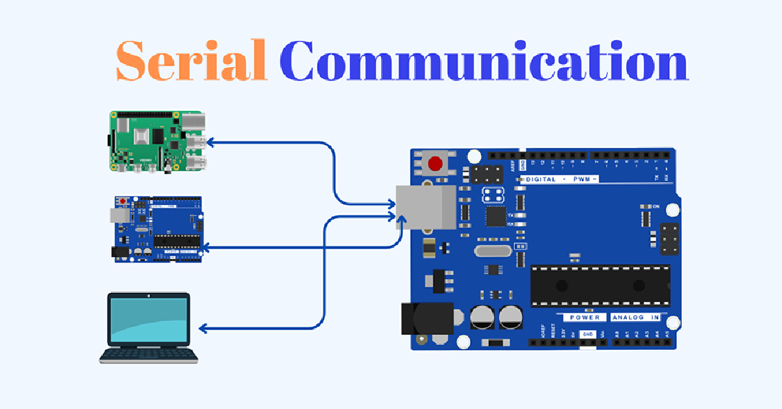
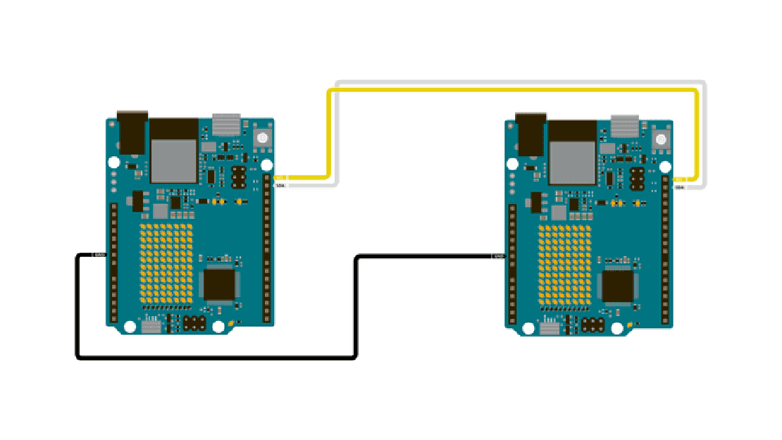
Demystifying UART, SPI, and I2C: Communication Between Chips
In both VLSI design and embedded systems, no chip operates in isolation. Whether it’s a microcontroller interfacing with sensors, a processor communicating with memory modules, or multiple peripherals synchronizing data, inter-chip communication is fundamental to building reliable and scalable hardware systems.
Read more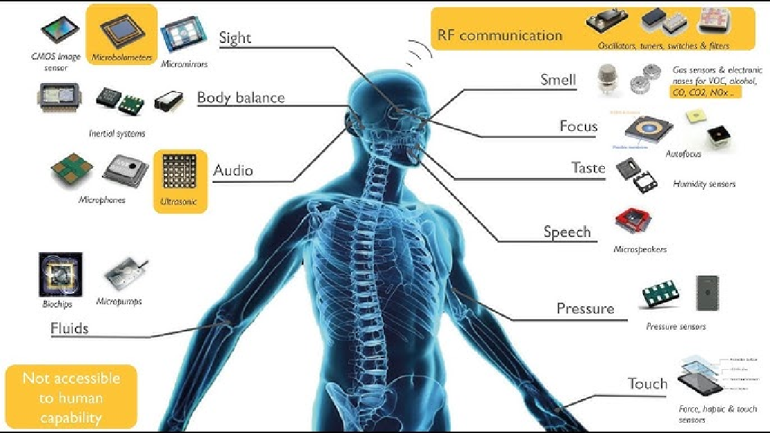
Sensors in Robotics: How Ultrasonic, LiDAR, and IMU Work
Sensors are to robots what eyes, ears, and skin are to humans—but with far fewer limits. While we rely on just five senses, robots can be equipped with many more, sensing distances, movement, vibrations, orientation, light intensity, and even chemical properties. These sensors form the bridge between the digital intelligence of a robot and the physical world it operates in.
Read more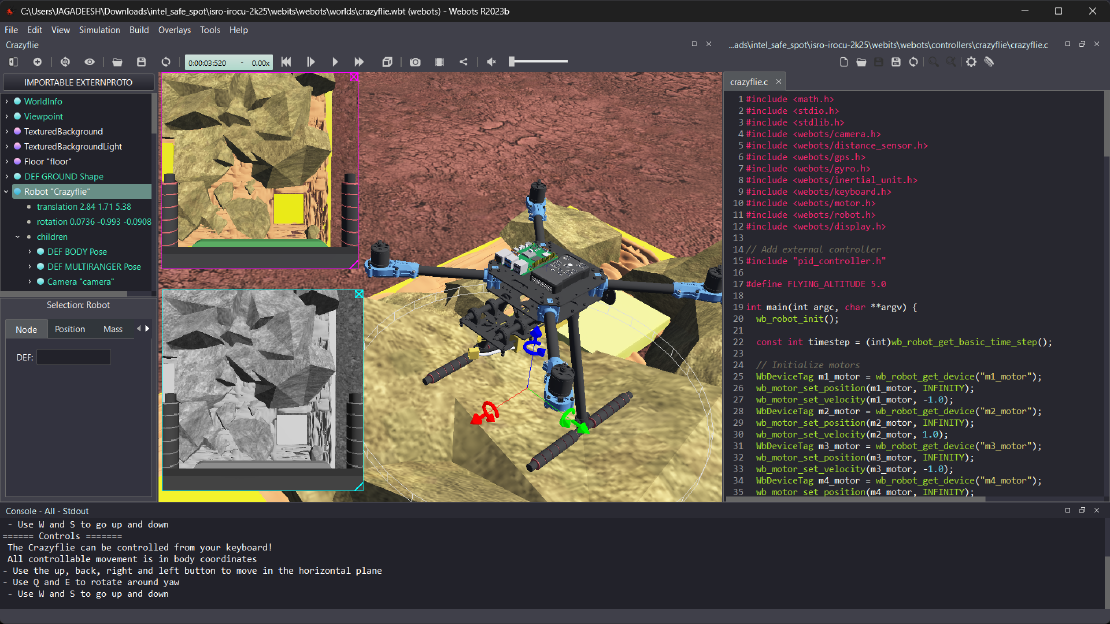
Debugging a Robot In Simulation Before You Burn Wires
Hardware does not come with an undo button. Once you power it on, mistakes—from reversed wiring to faulty code—can result in costly damage. Motors may overheat, printed circuit boards (PCBs) can be fried, and sensors may break. These issues turn exciting projects into frustrating repair sessions. The autonomous drone shown above, designed for GNSS-denied environments in webots as part of the ISRO Robotics Challenge, is a perfect example—where careful planning, testing, and hardware safety were critical at every step
Read more