

Sensors in Robotics: How Ultrasonic, LiDAR, and IMU Work
Sensors are to robots what eyes, ears, and skin are to humans—but with far fewer limits. While we rely on just five senses, robots can be equipped with many more, sensing distances, movement, vibrations, orientation, light intensity, and even chemical properties. These sensors form the bridge between the digital intelligence of a robot and the physical world it operates in.
Understanding how sensors work is critical to designing effective robotic systems. Whether it’s a self-balancing robot, an autonomous vehicle, a drone, or a robotic vacuum cleaner, sensing the environment is the first step toward autonomous behavior. In this post, we’ll explore how ultrasonic sensors, LiDAR, and IMUs function internally, what kinds of data they provide, and how they’re used across different robotic systems—from hobbyist builds to industrial automation and research-grade platforms.
Ultrasonic Sensors
Ultrasonic sensors are one of the most accessible and affordable distance-measuring tools used in robotics. They mimic echolocation, the same principle bats and dolphins use to “see” in the dark.
How Ultrasonic Sensors Work Internally
The core of an ultrasonic sensor includes:
- Transmitter: Emits ultrasonic sound waves (usually 40 kHz).
- Receiver: Listens for echoes bouncing back from nearby objects.
- Timing Circuit: Measures the time between sending and receiving the pulse.
When a microcontroller triggers the sensor, it sends out a pulse. The sound wave travels through the air, hits a surface, and reflects back. The time-of-flight is recorded, and with the known speed of sound (around 343 m/s), the distance is calculated.
At the heart of an ultrasonic sensor are piezoelectric transducers that convert electrical signals into mechanical vibrations (sound) and vice versa. The transmitter emits high-frequency sound waves (typically 40 kHz), which reflect off nearby objects and are captured by the receiver.
The key measurement is the time-of-flight $t$, which allows us to calculate the distance $d$ to the object using the equation:
$$ d = \frac{v \cdot t}{2} $$
Where:
- $v$ is the speed of sound in air (~343 m/s at 20°C),
- $t$ is the round-trip travel time of the pulse,
- The division by 2 accounts for the round trip.
The transducers are made of ceramic materials like lead zirconate titanate (PZT), which deform when voltage is applied (inverse piezoelectric effect), and generate voltage when deformed (direct effect). These are often mounted on a metal plate tuned for resonance.
Sensors like the HC-SR04 implement this in a very compact form factor, making them ideal for small robots.
Fabrication and Signal Processing
Internally, most modules include:
- Pulse generator circuit (typically a 555 timer or microcontroller),
- High-voltage driver for the transmitter (~80–100 V pulses),
- Amplifier and comparator for echo detection,
- Timing circuit or microcontroller to compute distances.
Noise filtering (both analog and digital) is crucial due to environmental interference and multipath echoes. Advanced ultrasonic sensors also use frequency modulation and chirp signals for better resolution in noisy environments.
Characteristics and Behavior
- Range: Typically from 2 cm to 400 cm.
- Field of View: Approximately 15° to 30°, depending on the model.
- Update Rate: Usually around 10–20 Hz.
- Surface Sensitivity: Struggles with soft, angled, or sound-absorbing materials.
Use Cases in Robotics
- Collision avoidance in indoor robots
- Wall-following behavior in maze-solving bots
- Height detection in drones during landing
- Presence detection for automatic doors
Common Types and Modules
- HC-SR04: Low-cost, simple interface (trigger and echo pins)
- MaxBotix EZ series: Analog and serial output, waterproof variants available
- Parallax Ping))): Single-pin interface, good for microcontroller integration
They’re often used in competitions like line-followers, Sumo bots, and micro-mouse challenges for close-proximity detection.
LiDAR (Light Detection and Ranging)
LiDAR revolutionizes robotic perception by creating precise, high-resolution maps of the environment using lasers. Unlike ultrasonic sensors, LiDARs are capable of measuring thousands of points per second.
Working Principle and Internal Architecture
At its core, LiDAR works by firing laser pulses and measuring the time it takes for each to bounce back from surrounding objects.
There are two primary mechanisms:
- Rotating Scanners: Use a spinning head to sweep the laser across a 2D or 3D field.
- Solid-State LiDARs: Use optical phased arrays or MEMS mirrors to steer laser beams without moving parts.
Data points are time-stamped and angular-position-tagged to create a point cloud, which is a detailed 2D or 3D map of the surroundings.
LiDARs generally operate in the near-infrared spectrum (around 850–1550 nm), and advanced models perform intensity correction and multi-echo analysis to detect partially transparent or low-reflectivity objects.
Use Cases Across Robotic Systems
- SLAM for autonomous navigation
- Terrain mapping for aerial drones
- Object detection and classification in self-driving cars
- Localization and collision avoidance in warehouse robots
In challenges like DARPA Urban Challenge or Amazon Picking Challenge, LiDAR has been central to navigation and environmental awareness.
Types of LiDAR and Their Operating Principles
Time-of-Flight LiDAR (ToF)
The simplest form, it emits short laser pulses and measures the return time. The distance $d$ is computed similarly to ultrasonic:
$$ d = \frac{c \cdot t}{2} $$
Where:
- $c$ is the speed of light (~3×10⁸ m/s),
- $t$ is the measured time-of-flight.
Because light travels so fast, even nanosecond delays matter. High-speed timing circuitry and avalanche photodiodes (APDs) are used for accurate detection.
Frequency-Modulated Continuous Wave (FMCW) LiDAR
Instead of pulsing, FMCW LiDAR emits a continuous laser whose frequency changes over time (chirp). When reflected light returns, it’s mixed with the transmitted signal, producing a beat frequency. This allows the sensor to calculate both distance and velocity, similar to radar.
FMCW is more resistant to ambient light and interference and is used in high-resolution automotive LiDARs.
Flash LiDAR
Flash LiDARs emit a single broad laser pulse and use a 2D photodetector array (e.g., CMOS or SPAD arrays) to capture the entire scene at once. No moving parts are needed, but the resolution is often lower than rotating models.
Fabrication and Components
Most rotating LiDARs use:
- Laser emitters (VCSELs or edge-emitting lasers),
- MEMS mirrors or spinning prisms for beam steering,
- Photodiodes or SPADs (single-photon avalanche diodes) for reception,
- High-frequency TDCs (Time-to-Digital Converters) for time measurements.
LiDARs must manage heat dissipation, eye safety (Class 1 lasers), reflectivity compensation, and synchronization in multi-LiDAR systems.
Coordinate Frames and Point Cloud Generation
As the LiDAR rotates or sweeps the laser across space, it tags each point with an angle $\theta$, elevation $\phi$, and range $r$. These are converted to Cartesian coordinates via:
$$ x = r \cdot \cos(\phi) \cdot \cos(\theta) \ y = r \cdot \cos(\phi) \cdot \sin(\theta) \ z = r \cdot \sin(\phi) $$
The result is a dense point cloud representing 3D surfaces in the environment. These are fed into algorithms like ICP (Iterative Closest Point) or NDT (Normal Distributions Transform) for localization and mapping.
Some LiDARs support ROS out-of-the-box, enabling seamless integration into SLAM, path-planning, and navigation stacks.
Inertial Measurement Units (IMUs)
While ultrasonic and LiDAR sensors detect the external environment, IMUs detect internal motion. They act like a robot’s inner ear, measuring how it moves, tilts, rotates, and accelerates in 3D space.
What’s Inside an IMU?
An IMU typically consists of:
- Accelerometers (3-axis): Detect linear movement or tilt.
- Gyroscopes (3-axis): Measure angular velocity.
- Magnetometers (optional): Measure magnetic fields to help determine orientation relative to Earth’s magnetic north.
Each of these components is based on micro-electro-mechanical systems (MEMS), where minuscule moving parts respond to inertia.
Advanced IMUs also include:
- Digital Signal Processors (DSPs) to fuse sensor data
- Temperature compensation mechanisms
- Calibration routines to correct biases and drift
Motion Tracking and Sensor Fusion
Raw sensor data can be noisy. To extract meaningful orientation (pitch, roll, yaw), systems apply fusion algorithms like:
- Complementary filters: Simple and fast, ideal for real-time use
- Kalman filters: Optimal estimation using uncertainty models
- Madgwick/Mahony filters: Lightweight quaternion-based filters for embedded systems
IMUs can report:
- Orientation: Useful for balancing robots
- Velocity and displacement: By integrating acceleration
- Heading direction: With magnetometer fusion
Applications in Robotics
- Flight stabilization in drones and quadcopters
- Dead reckoning in indoor mobile robots
- Motion tracking in robotic arms
- Gesture recognition in wearable robotics
- Balancing mechanisms in humanoid robots and self-balancing bots
Widely Used Modules
- MPU-6050: Affordable 6-axis IMU (gyro + accelerometer)
- MPU-9250: 9-axis with magnetometer
- BNO055: Sensor-fusion onboard, outputs orientation directly
- Xsens MTi series: Precision-grade used in robotics research, VR, and aerospace
In multi-sensor setups, the IMU fills in gaps where GPS, visual odometry, or LiDAR might be blind or slow—especially for fast-motion tracking or indoors.
Combining the Three: Sensor Fusion in Robotics
Robots almost never rely on a single sensor. Each sensor type has strengths and weaknesses. Combining multiple sensors allows for a more robust and accurate understanding of both the robot’s state and its environment.
Typical Multi-Sensor Stacks
Autonomous Ground Vehicles:
- LiDAR for 3D obstacle detection and SLAM
- IMU for estimating pose between LiDAR frames
- Ultrasonic for low-speed near-field collision avoidance
Aerial Drones:
- IMU for stabilization and flight dynamics
- Ultrasonic or LiDAR for ground-following
- GPS and magnetometer for outdoor localization
Mobile Robots (Indoors):
- LiDAR + IMU for accurate SLAM
- Ultrasonic for tight navigation in cluttered environments
- Wheel encoders for odometry
Sensor Fusion Algorithms
Data from IMU, LiDAR, and ultrasonic sensors can be fused using:
- Extended Kalman Filter (EKF): For localization
- Graph-based SLAM: For map building and loop closure
- Particle Filters: For uncertainty-based location estimation
Robotic frameworks like ROS provide built-in packages (e.g., robot_localization, cartographer, gmapping) to handle sensor fusion, time synchronization, and state estimation.
Final Thoughts
Sensors form the foundation of autonomy in robotics. Ultrasonic sensors help robots detect proximity with simple and cost-effective mechanisms. LiDAR delivers rich environmental mapping and spatial understanding. IMUs give robots a sense of their own movement and orientation. When used together, they transform a passive machine into a responsive, adaptive system capable of operating in complex, unpredictable environments.
Choosing the right combination of sensors depends on your robotic platform’s goals, budget, and operating environment. Understanding how each sensor works internally gives you the power to not just use them—but to trust them, tweak them, and optimize them for your own unique robotics challenges.
Related Posts
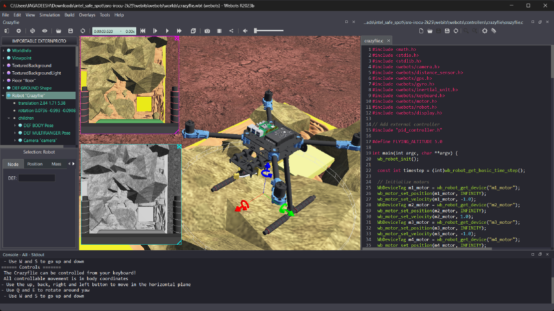
Debugging a Robot In Simulation Before You Burn Wires
Hardware does not come with an undo button. Once you power it on, mistakes—from reversed wiring to faulty code—can result in costly damage. Motors may overheat, printed circuit boards (PCBs) can be fried, and sensors may break. These issues turn exciting projects into frustrating repair sessions. The autonomous drone shown above, designed for GNSS-denied environments in webots as part of the ISRO Robotics Challenge, is a perfect example—where careful planning, testing, and hardware safety were critical at every step
Read more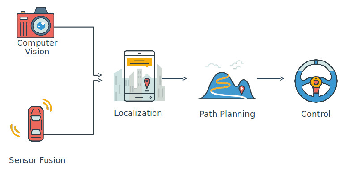
Computer Vision vs. Sensor Fusion: Who Wins the Self-Driving Car Race?
Tesla’s bold claim that “humans drive with eyes and a brain, so our cars will too” sparked one of the most polarizing debates in autonomous vehicle (AV) technology: Can vision-only systems truly compete with—or even outperform—multi-sensor fusion architectures?
Read more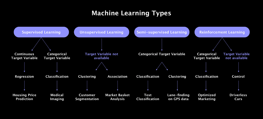
Understanding the Basics of Machine Learning
Machine learning is something that shows up all around us today—whether we’re aware of it or not. From personalized suggestions on YouTube and Netflix to automatic spam filtering in our inboxes, it’s quietly powering a lot of the tools we use daily.
Read more