
SPI: Understanding the Serial Peripheral Interface Protocol
SPI is a synchronous serial communication protocol designed for high-speed, full-duplex data exchange between a master device and one or more peripheral (slave) devices. It was originally developed by Motorola and remains widely adopted in microcontrollers, sensors, memory chips, ADCs/DACs, displays, and more.
Unlike UART, SPI uses a shared clock line, which allows for more precise timing, faster communication, and simpler hardware synchronization.
Fundamental Signal Lines
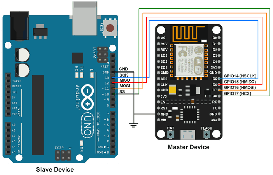
A typical SPI bus consists of four essential lines:
- SCLK (Serial Clock) – Generated by the master. Synchronizes data transfer.
- MOSI (Master Out Slave In) – Data sent from master to slave.
- MISO (Master In Slave Out) – Data sent from slave to master.
- SS or CS (Slave Select or Chip Select) – Active-low line used to select individual slave devices.
In a basic setup, the master controls the clock and selects which slave to talk to by asserting its dedicated CS line low. All data transmission is synchronized to the clock signal generated by the master.
Full-Duplex Operation
SPI is inherently full-duplex, meaning data can be transmitted and received simultaneously. Every clock pulse shifts one bit out on MOSI and one bit in on MISO.
This also means that every transmission is bi-directional, even if you only care about one direction (e.g., writing to a DAC—you still receive bits back, which are usually ignored).
Data Framing and Configuration Parameters
SPI doesn’t have a fixed data frame like UART. Instead, the configuration is flexible, and both master and slave must be set to agree on several parameters:
Clock Polarity (CPOL): Determines the idle state of the clock.
- CPOL = 0: Clock idles low
- CPOL = 1: Clock idles high
Clock Phase (CPHA): Defines on which clock edge data is sampled.
- CPHA = 0: Data sampled on the first clock edge
- CPHA = 1: Data sampled on the second clock edge
These two parameters define four SPI modes (Mode 0 to Mode 3). Master and slave must use the same mode:
| Mode | CPOL | CPHA | Clock Idle | Sample Edge |
|---|---|---|---|---|
| 0 | 0 | 0 | Low | Rising edge |
| 1 | 0 | 1 | Low | Falling edge |
| 2 | 1 | 0 | High | Falling edge |
| 3 | 1 | 1 | High | Rising edge |
Also configurable:
- Bit Order: MSB-first (default) or LSB-first
- Word Size: Usually 8 bits, but 16-bit, 32-bit, or arbitrary-length transfers are possible
Multi-Slave Topology
SPI supports multiple slaves, but with limitations:
- Independent CS lines: Each slave must have a dedicated chip-select line from the master. Only one CS line is asserted low at a time.
- Shared MISO/MOSI/SCLK: All other lines can be shared between devices.
Alternatives to reduce pin count:
- SPI daisy-chaining: Used in some chips (e.g., shift registers) where MISO of one device connects to MOSI of the next.
- Multiplexers or SPI expanders: Manage CS lines via GPIO expanders.
This makes SPI not truly multi-master or multi-drop—it’s a master-driven protocol with limited scalability in terms of wiring.
Electrical and Speed Characteristics
- No fixed electrical standard: Logic levels depend on devices (e.g., 3.3V, 5V). Always match or level-shift.
- No inherent error checking: Unlike UART or I2C, SPI has no parity, ACK/NACK, or CRC by default.
- Extremely fast: Speeds of 1–50+ Mbps are common. Some devices can go beyond 100 MHz.
Maximum reliable speed depends on:
- Bus capacitance (wiring length)
- PCB layout and impedance matching
- Slave device timing limitations (check datasheets)
Advantages of SPI
- High speed: Ideal for large data throughput (e.g., sensors, memory, screens)
- Simple hardware: No addressing or arbitration logic
- Full-duplex: Allows simultaneous send/receive
- Flexible data word size: Can send arbitrary-length packets
- No protocol overhead: Efficient raw data transfer
Limitations
- No standard device addressing: Requires separate CS per slave or custom protocol
- No error detection or correction: Needs to be implemented at the application layer
- Requires more wires: 4 signals minimum, plus extra CS lines for more slaves
- Single master only (in most practical implementations)
Flow Control and Interrupts
SPI typically does not use flow control. The master initiates all communication and must ensure that:
- The slave is ready (by polling a READY pin or delay)
- Data is handled fast enough (especially for high-speed transfers)
Slaves may offer:
- READY/BUSY lines: Optional GPIO used by the slave to signal status
- DMA support: Offloads high-speed SPI to memory without CPU intervention
Applications and Use Cases
SPI is preferred when speed and efficiency are key. Typical applications include:
- Flash memory chips (e.g., NOR, NAND)
- SD cards (in SPI mode)
- LCD/OLED display modules
- High-speed ADCs and DACs
- Real-time sensors (gyroscopes, accelerometers)
- Audio CODECs (I2S is a variant of SPI)
Many sensors come in both SPI and I2C versions, letting designers choose between higher performance (SPI) or fewer wires (I2C).
Debugging SPI
Debugging SPI can be trickier than UART because it’s clocked and often involves multiple devices. Use:
Logic analyzers (Saleae, Logic Pro) to decode SPI frames
Oscilloscopes to confirm proper edge alignment (especially CPOL/CPHA)
Check for:
- Misconfigured SPI mode
- Incorrect bit order
- Bad CS handling (glitches, multiple CS active)
- Slave not responding (often a sign of CS or mode mismatch)
Conclusion
SPI is a powerful and versatile protocol, especially when speed, simplicity, and full-duplex operation are required. Though it doesn’t scale well in large multi-device systems and lacks built-in error checking, its deterministic timing, low protocol overhead, and wide support make it an essential tool in any embedded engineer’s arsenal.
Whether you’re streaming data to a display, reading high-speed sensors, or managing memory chips, SPI provides a direct and efficient path for raw, fast communication.
Related Posts
Demystifying UART, SPI, and I2C: Communication Between Chips
In both VLSI design and embedded systems, no chip operates in isolation. Whether it’s a microcontroller interfacing with sensors, a processor communicating with memory modules, or multiple peripherals synchronizing data, inter-chip communication is fundamental to building reliable and scalable hardware systems.
Read more
Sensors in Robotics: How Ultrasonic, LiDAR, and IMU Work
Sensors are to robots what eyes, ears, and skin are to humans—but with far fewer limits. While we rely on just five senses, robots can be equipped with many more, sensing distances, movement, vibrations, orientation, light intensity, and even chemical properties. These sensors form the bridge between the digital intelligence of a robot and the physical world it operates in.
Read more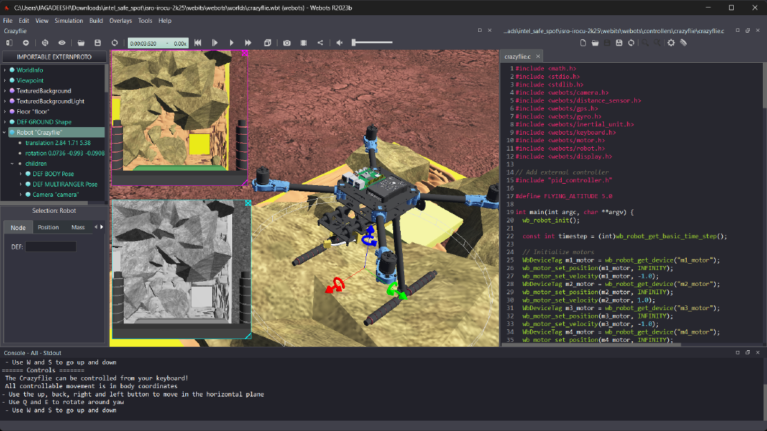
Debugging a Robot In Simulation Before You Burn Wires
Hardware does not come with an undo button. Once you power it on, mistakes—from reversed wiring to faulty code—can result in costly damage. Motors may overheat, printed circuit boards (PCBs) can be fried, and sensors may break. These issues turn exciting projects into frustrating repair sessions. The autonomous drone shown above, designed for GNSS-denied environments in webots as part of the ISRO Robotics Challenge, is a perfect example—where careful planning, testing, and hardware safety were critical at every step
Read more