
UART: A Detailed Overview of Asynchronous Serial Communication
UART is one of the oldest and most fundamental methods of serial communication in embedded systems. As its name suggests, it operates asynchronously, meaning there is no shared clock signal between the transmitter and the receiver. This makes UART especially attractive in scenarios where simplicity and minimal wiring are important.
Fundamental Concept
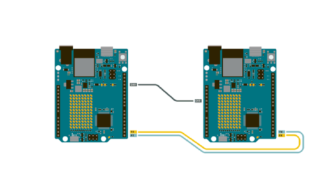
In a UART communication system, data is transmitted serially, bit by bit, over a single wire (TX), and received on another (RX). Each device in the communication link has its own internal clock, and both must agree on a common baud rate (bits per second). Because there’s no external clock signal, this baud rate agreement is critical—if either side drifts too much, communication breaks down.
Data Framing Structure
Every UART frame consists of several components to delimit and validate the transmission:
- Start bit – Marks the beginning of a data frame. It’s always a logic 0 (low).
- Data bits – Typically 5 to 9 bits, though 8 bits is most common. Sent LSB-first.
- Optional parity bit – Used for rudimentary error checking (even or odd parity).
- Stop bit(s) – One or more bits of logic 1 (high) to signal the end of the frame.
A typical 8-N-1 UART frame (8 data bits, no parity, 1 stop bit) looks like this:
Line Idle: HIGH
↓
Start Bit (0) → [D0 D1 D2 D3 D4 D5 D6 D7] → Stop Bit (1)
During idle periods (no transmission), the line remains at logic high.
Baud Rate and Timing Constraints
Since UART is asynchronous, both ends must know the exact baud rate—for example, 9600, 115200, or even up to a few Mbps depending on hardware. A mismatch in baud rate beyond ~2-3% can lead to framing errors.
For example, at 9600 baud:
- Each bit lasts ~104.17 microseconds.
- A full 10-bit frame (start + 8 data + stop) takes ~1.04 ms.
UART receivers usually oversample the incoming data line (commonly at 16× the baud rate) to detect the start bit and sample data bits at the correct time.
Error Detection and Robustness
UART includes minimal error handling:
- Parity Bit (optional): Basic check for single-bit error detection.
- Framing Error: If the stop bit isn’t logic high at the expected time.
- Overrun Error: If the receiver buffer isn’t read fast enough and gets overwritten.
- Break Condition: If the line is held low for longer than a full frame—used to signal an intentional interruption.
Due to the lack of built-in CRC or acknowledgment schemes, higher-layer protocols (like Modbus, NMEA, or custom ones) often wrap UART transmissions with additional error-checking logic.
Flow Control Mechanisms
When sending variable-sized or fast streams of data, there’s a risk of buffer overflow. To mitigate this:
- Software Flow Control: Special characters like XON (0x11) and XOFF (0x13) are sent to pause/resume transmission.
- Hardware Flow Control: Uses additional lines like RTS (Request to Send) and CTS (Clear to Send) for handshake.
These features are not part of the UART standard itself but are often implemented by UART peripherals or bridges (e.g., USB-to-UART chips).
Electrical Characteristics
UART is purely a signaling protocol—it doesn’t define voltage levels. Typical implementations use:
- TTL logic levels: 0V (low), 5V or 3.3V (high)
- RS-232: ±12V for signaling (used in PCs, legacy serial ports)
Make sure voltage levels match between devices or use level shifters to avoid damage.
Topology and Limitations
UART supports only point-to-point communication. You cannot have more than two devices on the same TX/RX lines without a multiplexer or external logic.
This makes UART unsuitable for multi-device networks unless augmented with switches, hubs, or protocol conversion (e.g., UART-to-I2C/SPI bridges or USB).
Buffering and Interrupts
Most modern microcontrollers include a UART peripheral with internal FIFO buffers (commonly 16, 32, or 64 bytes). This allows temporary storage of incoming/outgoing bytes to decouple hardware timing from software response.
Reception can be handled via:
- Polling – CPU actively checks status register
- Interrupts – ISR is triggered when data is received
- DMA (Direct Memory Access) – High-speed, CPU-independent transfer
Applications and Use Cases
UART is used everywhere, especially in scenarios where:
Only two devices need to communicate
Simple, low-speed data exchange is sufficient
Debugging via serial terminals (e.g.,
printfover UART)Communication with modules like:
- GPS receivers
- GSM modems
- Bluetooth (e.g., HC-05)
- Serial LCDs or displays
- USB-to-serial bridges (e.g., FT232, CH340)
Typical Baud Rates and Limitations
| Common Baud Rates | Notes |
|---|---|
| 9600 | Very common, reliable |
| 38400 | Used in some industrial devices |
| 115200 | Common for debugging/logging |
| 1 Mbps+ | Achievable on high-performance MCUs |
The upper limit depends on:
- Clock accuracy
- Signal integrity (cable length, crosstalk)
- Peripheral and driver capability
Debugging UART
Troubleshooting UART issues often involves:
- Checking baud rate configuration (both sides must match)
- Monitoring line using an oscilloscope or logic analyzer
- Using tools like PuTTY, minicom, or serial monitor in IDEs
- Verifying no framing or parity errors
- Ensuring buffers aren’t overflowing (especially on RX)
Conclusion
UART is simple, efficient, and nearly universal. Its asynchronous nature makes it easy to use with just two wires, but that simplicity comes at the cost of scalability and robustness. While not ideal for high-speed or multi-device communication, it remains indispensable for low-complexity, point-to-point data exchange.
Whether you’re printing debug logs or interfacing with legacy peripherals, understanding UART deeply is foundational for any embedded system designer.
Related Posts
Demystifying UART, SPI, and I2C: Communication Between Chips
In both VLSI design and embedded systems, no chip operates in isolation. Whether it’s a microcontroller interfacing with sensors, a processor communicating with memory modules, or multiple peripherals synchronizing data, inter-chip communication is fundamental to building reliable and scalable hardware systems.
Read more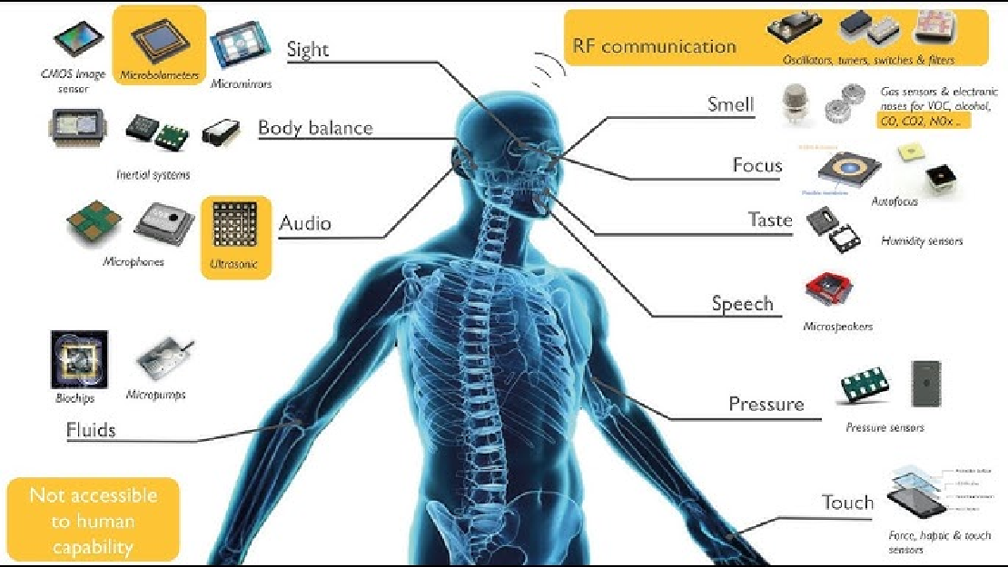
Sensors in Robotics: How Ultrasonic, LiDAR, and IMU Work
Sensors are to robots what eyes, ears, and skin are to humans—but with far fewer limits. While we rely on just five senses, robots can be equipped with many more, sensing distances, movement, vibrations, orientation, light intensity, and even chemical properties. These sensors form the bridge between the digital intelligence of a robot and the physical world it operates in.
Read more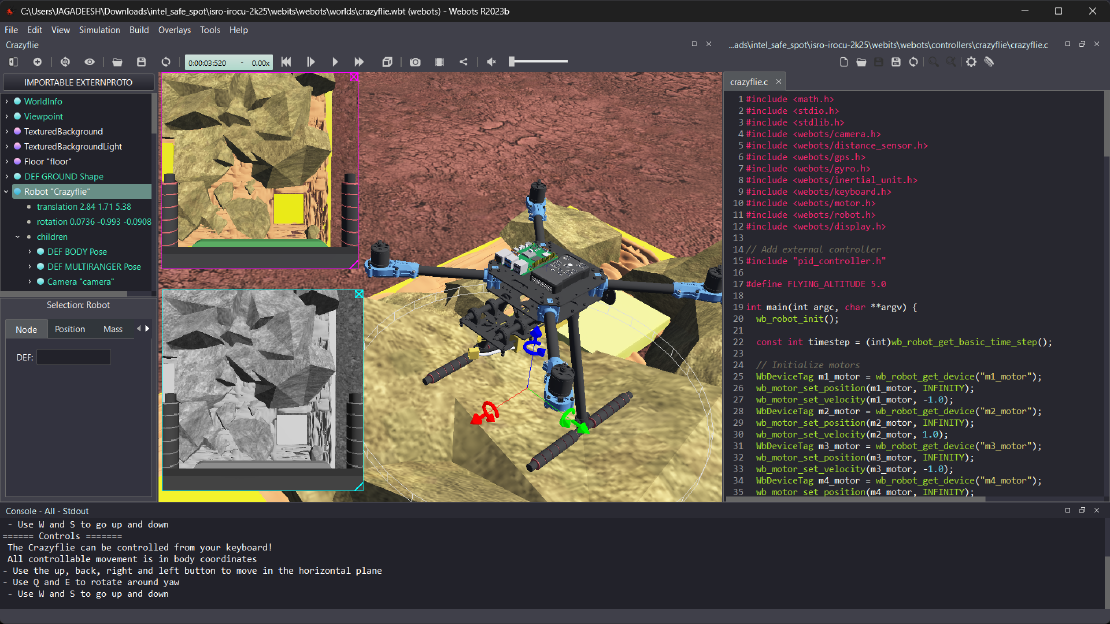
Debugging a Robot In Simulation Before You Burn Wires
Hardware does not come with an undo button. Once you power it on, mistakes—from reversed wiring to faulty code—can result in costly damage. Motors may overheat, printed circuit boards (PCBs) can be fried, and sensors may break. These issues turn exciting projects into frustrating repair sessions. The autonomous drone shown above, designed for GNSS-denied environments in webots as part of the ISRO Robotics Challenge, is a perfect example—where careful planning, testing, and hardware safety were critical at every step
Read more