

My First Tiny Tapeout: Building a Digital PLL on Sky130
Tiny Tapeout is a shared multi-project wafer service. You submit a small digital design, it gets placed on a tile alongside hundreds of others, and the whole thing goes to a foundry on the SkyWater 130 nm open-source process. Each participant gets a rectangular slice of the die routed to a standardised interface. A 1x1 tile is roughly 160 by 100 micrometres of core area. You write RTL, push to a GitHub repository, the CI runs OpenLane against your design, and if placement and routing close within the tile boundary you get a GDS file. If the shuttle fills, that GDS goes to the fab.
The submission is a Digital Phase-Locked Loop: closed-loop phase and frequency tracking, lock detection, and synchronisation, implemented in a compact fully-synchronous digital datapath. Getting there involved an earlier attempt at a CORDIC-based FFT accelerator that did not survive the area constraints. That story is at the end.
Background
The CORDIC core used throughout this project is part of a larger standalone IP covering all six canonical modes across circular, linear, and hyperbolic coordinate systems, formally verified with SymbiYosys. The FFT, IFFT, QAM16 demodulator, Sigma-Delta ADC, and this DPLL are all application demonstrations built on top of that same core.
CORDIC core: standalone verification before reuse
Before the CORDIC was connected to anything, a set of standalone checks established that the core itself behaved correctly under all conditions. These carried forward into the DPLL without repetition.
Handshake correctness. The start/busy/valid protocol was verified under back-to-back transactions (new start issued immediately after valid deasserts) and under spaced transactions with arbitrary gaps. In both cases: busy asserts on the cycle after start, valid pulses exactly once per computation, busy deasserts on the same cycle valid asserts.
Deadlock freedom and progress. Every start pulse that finds busy deasserted reaches valid within exactly ITER + 2 cycles.
Monotonic iteration progress. The iteration counter was verified to increment by exactly one per clock cycle while busy is asserted, from 0 to ITER - 1, with no skips or repeats.
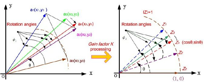
Rotation accuracy. Circular rotation mode was verified across angles spanning the convergence domain $|\theta| < \pi/2$. The $x$ and $y$ outputs converge to $\cos\theta$ and $\sin\theta$ within the Q1.30 quantisation floor at ITER=16.
Back-to-back stability. 50 consecutive transactions at varying angles with no idle cycles. No state leaked between transactions.
Quadrant symmetry. $\cos(-\theta) = \cos(\theta)$, $\sin(-\theta) = -\sin(\theta)$, and folded-angle outputs consistent with expected negation behaviour at boundaries.
The DPLL
Architecture
The DPLL is a second-order fully-synchronous digital phase-locked loop. All angular quantities are Q2.30 throughout the datapath. No floating-point arithmetic appears anywhere.
ref_i / ref_q (Q1.30 unit-amplitude complex phasor)
|
v
[ref_i_hold / ref_q_hold] latched at valid_in
| stable for ITER+3 cycles during CORDIC compute
|
v +---------------------------------------+
[cordic_nco] <-- phase_inc | phase_acc += phase_inc |
| <-- freq_adj | + freq_adj |
| <-- phase_adj | + phase_adj (one-shot)|
| (delayed) | CORDIC rotation -> cos / sin |
| +---------------------------------------+
| nco_i / nco_q (Q1.14)
v
[dpll_phase_det] <-- ref_i_hold / ref_q_hold
|
| cross = Im{ conj(nco) x ref } (Q2.30)
| = (nco_i x ref_q - nco_q x ref_i) >> 14
v
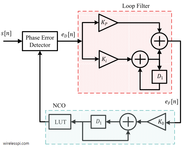
[dpll_loop_filter] PI filter
|
| integrator += KI x cross -> freq_adj (persistent)
| phase_adj = KP x cross (one-shot)
|
| freq_locked : |delta_freq_adj| < 0.001 rad/sample for 64 samples
| phase_locked : |phase_err| < sin(5deg) x 2^30 for 64 samples
| locked : freq_locked AND phase_locked
v
[adj_valid delayed 4 cycles] -> phase_adj_en in cordic_nco
Numerically controlled oscillator
The NCO maintains a 64-bit signed phase accumulator. A 33-bit accumulator would technically hold $\pm\pi$ in Q2.30, but TWO_PI = 6.75e9 exceeds the signed 33-bit range of 4.3e9, making wrap arithmetic unsafe at the extremes. The 64-bit accumulator avoids overflow at negligible synthesis cost.
Phase wrapping to $(-\pi, \pi]$ happens combinationally before each CORDIC invocation. The NCO then folds the wrapped phase into $(-\pi/2, \pi/2]$ to stay within the CORDIC convergence domain. A quadrant-negation flag is registered and applied to the output to recover correct cosine and sine for all four quadrants.
One design choice that mattered significantly: the CORDIC is launched on the next phase accumulator value, computed combinationally, rather than the registered previous value. Without this look-ahead, the NCO introduces a one-sample lag of phase_inc per clock. Over a long sequence under a nonzero frequency offset, this lag accumulates in the loop integrator as a constant residual error, driving the phase trajectory toward a fold boundary and producing false equilibria.
Phase adjustments from the loop filter are latched separately and consumed atomically on the next NCO enable pulse, which prevents a race between the feedback write and the accumulator read.
The NCO outputs cos/sin in Q1.14, right-shifted by 16 from the full Q1.30 CORDIC output. This keeps all phase detector partial products within 64 bits without additional scaling.
Phase detector
The phase detector computes the imaginary part of $\text{conj}(\text{nco}) \times \text{ref}$:
$$\text{cross} = (r_q \cdot n_i - r_i \cdot n_q) \gg 14$$A positive cross product means ref leads nco. The loop responds by speeding up the NCO.
The shift of 14 rather than 16 is where the normalisation lives. ref is Q1.30 (amplitude $= 2^{30}$) and nco is Q1.14 (amplitude $= 2^{14}$). Their product is Q2.44. Shifting right by 14 gives Q2.30, normalised so that cross $= 2^{30}$ when $\sin(\text{error}) = 1$. Shifting by 16 instead gives Q2.28, which is $4\times$ too small. The integrator settles at a false nonzero freq_adj rather than converging to zero, and the locked signal asserts anyway. This was the hardest bug to diagnose: the loop appeared locked, but freq_adj was offset from the correct value by a constant proportional to the frequency offset. Confirming the root cause required analytically computing what the cross-product should equal at $\sin(\text{err})=1$ and verifying it was $2^{28}$ with MUL_SH=16 rather than $2^{30}$.
Two phase detector modes are available. PD_MODE=0 (default) uses the direct cross-product with 1-cycle latency, correct sign for all $|\text{error}| < 180°$. PD_MODE=1 computes full $\text{atan2}$ via CORDIC vectoring. This is not suitable for free-running operation: CORDIC preconditioning negates both x and y when $x < 0$, making 0° and 180° indistinguishable and producing false lock at $\pm 180°$. PD_MODE=1 is suitable for decision-directed loops where symbol decisions resolve the ambiguity.
Loop filter
Standard second-order PI structure:
$$\text{integrator} \mathrel{+}= K_I \cdot \text{phase_err} \quad \to \quad \text{freq_adj}$$$$\text{phase_adj} = K_P \cdot \text{phase_err}$$Both multiplications sign-extend their 32-bit operands to 64 bits before multiplying. Without this, Verilog sizes a $32 \times 32$ product to 32 bits, truncating the result before the right-shift. ki_term and kp_term are always approximately zero, and the integrator never moves. This was the first bug encountered in the loop filter: it silently did nothing.
The integrator is clamped to $\pm 0.1$ rad/sample ($\pm 107374182$ in Q2.30). This limits maximum frequency correction to the expected acquisition range and prevents large integrator excursions during cold start. An earlier clamp at $\pm \pi$ allowed the integrator to wander past the correct value and settle in a false equilibrium where the oscillating phase error averaged to zero over full phase rotations.
Dual lock detection. Two independent counters run simultaneously:
| Signal | Condition | Threshold |
|---|---|---|
freq_locked | integrator has stabilised | $ |
phase_locked | phase error is small | $ |
locked | true synchronisation | freq_locked AND phase_locked |
The dual criterion eliminates the class of false lock where freq_locked fires because the integrator stops changing while the NCO is running at the wrong frequency and the phase error oscillates through full cycles.
Parameters
Gains derived from second-order PLL design with natural frequency $\omega_n = 0.01$ rad/sample and damping ratio $\zeta = 0.707$:
$$K_P = 2\zeta\omega_n = 0.014 \quad \to \quad 15182709 \text{ in Q2.30}$$$$K_I = \omega_n^2 = 0.0001 \quad \to \quad 107374 \text{ in Q2.30}$$| Parameter | Default | Float Equiv. | Description |
|---|---|---|---|
WIDTH | 32 | - | Datapath width |
ITER | 16 | - | CORDIC iterations |
PD_MODE | 0 | - | 0 = cross-product, 1 = atan2 |
KP | 15182709 | 0.014 | Proportional gain |
KI | 107374 | 0.0001 | Integral gain |
LOCK_COUNT | 64 | - | Consecutive samples for lock |
Fixed-point format
| Signal | Format | Notes |
|---|---|---|
ref_i, ref_q | Q1.30 | Unit amplitude input phasor |
phase_inc, freq_adj, phase_adj | Q2.30 | Angular quantities, rad/sample |
nco_i, nco_q | Q1.14 | After >> 16 from CORDIC Q1.30 output |
phase_err | Q2.30 | $\sin(\text{error})$, normalised by MUL_SH=14 |
| Integrator | 64-bit | Anti-windup clamped to $\pm 0.1 \times 2^{30}$ |
| CORDIC internal | Q1.30 | WIDTH=32, ITER=16 |
Timing details
Two timing concerns in the top-level integration required explicit handling.
ref_i_hold: The reference phasor is latched at valid_in and held stable for the duration of the NCO computation. The NCO takes ITER + 3 cycles to produce output. Without the hold register, the phase detector compares the wrong reference sample against the NCO output.
adj_valid 4-cycle delay: adj_valid fires 2 cycles after nco_valid. In back-to-back operation, the next valid_in arrives immediately after nco_valid. Without the delay, adj_valid and en arrive at the NCO simultaneously and the phase_adj latch guard discards the correction silently every single sample. Delaying adj_valid by 4 cycles, which is negligible relative to ITER=16, ensures phase_adj is safely latched before the next NCO computation begins.
freq_adj is not delayed. It is a persistent wire applied every NCO cycle unconditionally. Only phase_adj (one-shot proportional correction) needs the delayed enable.
Tiny Tapeout interface
The design is accessed through a byte-command serial interface matching the Tiny Tapeout IO constraints.
Inputs:
ui_in[7:0]: data byteuio_in[7]: command strobeuio_in[6:4]: command iduio_in[3:0]: argument nibble
Output:
uo_out[7:0]: status/data byte
Command map:
| CMD | Function |
|---|---|
0 | Write ref_i byte lane |
1 | Write ref_q byte lane |
2 | Write phase_inc byte lane |
3 | Control: arg[2] sets run_enable from arg[1], arg[0] single-step pulse, arg[3] clears latched valid |
4 | Set read selector |
5 | Set read byte lane |
6 | Output mode: arg[0] selects status/data, arg[1] clears latched valid |
Read selectors:
| Selector | Signal |
|---|---|
0 | nco_i_full |
1 | nco_q_full |
2 | ref_i |
3 | ref_q |
4 | phase_inc |
5 | nco_i |
Programming a DPLL update means: writing ref_i, ref_q, and phase_inc byte-by-byte through CMD 0-2, issuing a start via CMD 3, waiting for done_latched in the status byte, then reading back NCO outputs via CMD 4-5. The byte-lane protocol allows full 32-bit word access over an 8-bit bus without any changes to the DPLL datapath.
Bugs found during development
Each of these represents a recurring class of fixed-point RTL pitfall. The symptom in most cases was not obviously traceable to the root cause.
| # | Module | Bug | Symptom | Fix |
|---|---|---|---|---|
| 1 | dpll_phase_det | Cross product sign inverted: p_iq - p_qi instead of p_qi - p_iq | Loop diverged on startup | Flip operands |
| 2 | dpll_loop_filter | 32x32 multiply result sized to 32 bits by Verilog before shift | ki_term always ~0; integrator never moved; loop appeared stuck | Sign-extend both operands to 64 bits before multiplying |
| 3 | dpll_phase_det | MUL_SH=16 gave Q2.28 output instead of Q2.30 | Integrator settled at constant nonzero freq_adj; locked asserted at wrong frequency | Change MUL_SH = NCO_SH - 2 = 14 |
| 4 | dpll | adj_valid and en arrived at NCO simultaneously | Every phase_adj correction silently dropped | Delay adj_valid by 4 cycles |
| 5 | dpll / gains | KP=0.1, KI=0.005, 10x too large | Loop overshot, settled in false equilibrium; locked asserted at wrong frequency | Reduce to KP=0.014, KI=0.0001 |
| 6 | dpll_loop_filter | Anti-windup clamped at $\pm\pi$ | Integrator wandered into false equilibria during large offsets | Tighten clamp to $\pm 0.1$ rad/sample |
Bug 3 was the most difficult to isolate. The symptom was identical to Bug 5, and both occurred simultaneously in the same run. Distinguishing them required isolating the phase detector output scaling independently of the gain values. The cross-product at $\sin(\text{err})=1$ should equal $2^{30}$ for a Q2.30-normalised detector. With MUL_SH=16 it was $2^{28}$, confirmed analytically before any gain changes were made.
Physical design
Pre-synthesis area evaluation
Before committing to a tile size or pushing through the full OpenLane flow, the design was evaluated locally with Yosys against the sky130 standard cell library. Running synthesis with the synth pass followed by stat on the flattened netlist gives a cell-level area breakdown that is fast to iterate on and cheap to re-run after any RTL change. This pre-evaluation pass is what made tile selection deliberate rather than guesswork.
The area breakdown from that pass identified the CORDIC core as the dominant contributor by a wide margin. At WIDTH=32 and ITER=16, it synthesises to a deep combinational fabric: 16 shift-add iterations, each a 32-bit adder pair with wired shifts and an arctan constant lookup. The xnor2 and xor2 populations in the final stat report (1,792 and 703 instances respectively) are the direct signature of this — those cells are the arithmetic core of the CORDIC datapath. Everything else in the design, the phase detector, loop filter, PI integrator, wrapper state machine, is small sequential logic by comparison. The CORDIC iteration registers account for the bulk of the 613 flip-flop instances, with the 64-bit accumulator and PI integrator contributing the remainder. Sequential logic represents 8.91% of total chip area; the rest is combinational.
With that breakdown in hand, three tile sizes were evaluated against the flattened post-synthesis cell area:
| Tile | Envelope | Raw utilisation |
|---|---|---|
| 4x2 | 144,288 µm² | ~92.5% |
| 6x2 | 216,432 µm² | ~61.7% |
| 8x2 | 288,576 µm² | ~46.3% |
The 4x2 envelope leaves almost no routing margin. At PL_TARGET_DENSITY_PCT=60, the required available area is approximately 222,000 µm², which eliminates both the 4x2 and 6x2 options before a single OpenLane run. The 8x2 tile at ~46% raw utilisation was the correct starting point, not arrived at by trial and error through failed CI runs.
Placement and routing
OpenLane ran against the 8x2 tile with PL_TARGET_DENSITY_PCT=60, CLOCK_PERIOD=20ns, and hold slack margins of 0.1ns (resizer) and 0.05ns (global router). The post-CTS resizer inserted 201 setup buffers and 261 hold buffers to repair timing across the placed netlist, with 2,255 timing repair buffers total bringing the final stdcell count to 24,151 at 68.2% core utilisation. Mean instance displacement during repair was 0.29µm with a maximum of 30.9µm, indicating the placer did not need to move cells aggressively to close timing. There were zero design violations post-CTS.
The CORDIC datapath drives the routing complexity. Sixteen iterations of 32-bit shift-add through a fully combinational pipeline produces long, wide logic cones with high fanout on the iteration counter and shift-select signals. The global router saw an estimated wirelength of 642,938µm after CTS. Detailed routing converged across three DRT iterations with no DRC violations in the final pass.
Seven warnings were logged: one RSZ-0062 from the resizer and six STA-1140 unconstrained path warnings on ports that intentionally carry no timing constraint in the Tiny Tapeout wrapper interface.
Timing closure
Post-route STA was run across nine PVT corners with extracted parasitics. At the nominal corner (tt/25°C/1.8V) both setup and hold close with zero negative slack. Hold closes cleanly across all corners including the worst-case slow-slow/100°C/1.6V/max-parasitics corner, which is the result of the hold buffer insertion done post-CTS. Setup violations at the SS corner are expected given the CORDIC’s combinational depth: a 16-stage shift-add chain through 32-bit datapaths is a genuinely long path, and the SS corner at elevated temperature and reduced voltage applies the most pessimistic characterisation possible. The design operates at typical conditions on the Tiny Tapeout shuttle.
Final CI run
gds:      PASS
precheck: PASS
gl_test:  PASS
viewer:   PASS
GDS

The 8x2 tile with the DPLL placed and routed. The CORDIC core is visible as a distinct combinational cluster towards the centre-left, consistent with its dominance of the cell area budget. Power rails run horizontally across the tile. Tiny Tapeout IO pads connect at the right edge.
3D viewer
Verification
Four independent verification strategies were applied. Each covers a different dimension of correctness, and together they span numerical accuracy, protocol correctness, coverage closure, and formal property proofs.
Python golden numerical verification
The golden numerical suite runs the DPLL model against a Python reference implementation, comparing output trajectories sample by sample. The key metric is whether freq_adj converges to the correct value and stays there. The observed NCO magnitude error sits near the numerical floor for the configured fixed-point path.
Five directed tests, 2000 samples each. Pass criterion: locked == True AND $|\text{freq_adj} - (\text{ref_freq} - \text{nom_freq})| < 0.0001$ rad/sample.
| Test | Nom Freq | Ref Freq | Init Phase | Expected freq_adj | Lock Sample | freq_adj Error |
|---|---|---|---|---|---|---|
| Ideal | 0.2 | 0.2 | 0.0 rad | 0.000000 | 149 | 8.48e-08 |
| Phase +0.5 rad | 0.2 | 0.2 | +0.5 rad | 0.000000 | 78 | 4.38e-08 |
| Freq +0.005 | 0.2 | 0.205 | 0.0 rad | +0.005000 | 437 | 1.03e-07 |
| Freq +0.015 | 0.2 | 0.215 | 0.0 rad | +0.015000 | 478 | 1.60e-07 |
| Combined +0.003/+0.3 | 0.2 | 0.203 | +0.3 rad | +0.003000 | 350 | 4.23e-08 |
============================================================
  DPLL Testbench  WIDTH=32  ITER=16
  KP=0.014  KI=0.0001  LOCK_COUNT=64
============================================================
  [Ideal              ]  locked=True  lock_samp= 149  err=8.48e-08  PASS
  [Phase +0.5 rad     ]  locked=True  lock_samp=  78  err=4.38e-08  PASS
  [Freq +0.005        ]  locked=True  lock_samp= 437  err=1.03e-07  PASS
  [Freq +0.015        ]  locked=True  lock_samp= 478  err=1.60e-07  PASS
  [Combined +0.003/0.3]  locked=True  lock_samp= 350  err=4.23e-08  PASS

  Directed: 5 PASS  0 FAIL
The freq_adj errors are Q2.30 register quantisation residuals. 1 LSB $= 9.3 \times 10^{-10}$ rad/sample; the observed residuals of ~70-170 LSBs represent the loop dithering around the nearest representable value, not a real tracking error.
The Phase +0.5 rad test locks faster than the Ideal test (78 vs 149 samples) because a large initial phase error drives stronger proportional correction during acquisition, pulling freq_adj to zero faster despite a zero frequency offset.
Acquisition range sweep. 21 frequency offsets from +0.000 to +0.040 rad/sample, all pass. First failure at +0.042 (error = 1.95e-4, just above threshold). The pull-in boundary at 0.040 rad/sample follows from the anti-windup clamp: INT_MAX = 0.1 rad/sample, and for this loop the practical acquisition range is approximately INT_MAX * 0.4.
  foff=+0.000 to +0.040:  locked=True, err < 1e-4  (all 21 points pass)
  foff=+0.042:  err=1.95e-4  FAIL
  Max acquisition range: 0.040 rad/sample
Lock time distribution. 50-seed sweep at foff=0.005 rad/sample: mean=506.7 samples, min=233, max=810. The spread is caused by initial phase; a phase that creates a large initial proportional correction can accelerate or retard convergence significantly.
Phase offset tolerance. 25 initial phases from 0° to 180°, all pass, including exactly 180°, which is the ambiguous point that produces false lock in PD_MODE=1. Residual freq_adj error after convergence is in the range $10^{-8}$ to $10^{-7}$ rad/sample across all phases, with no systematic trend.
Steady-state frequency accuracy. 26 offsets from 0 to 0.025 rad/sample in steps of 0.001. Max error $9.93 \times 10^{-8}$ rad/sample, mean error $6.30 \times 10^{-8}$ rad/sample. All 26 points within the $10^{-4}$ pass threshold, with approximately 3 orders of magnitude of margin.
  Max error  : 9.93e-08 rad/sample
  Mean error : 6.30e-08 rad/sample
  All within 1e-4: True
Functional verification (cocotb)
The cocotb suite drives the design through the Tiny Tapeout byte-command wrapper interface, the same path the physical chip will use. Tests are not aware of internal architecture; they only see the IO protocol.
Tests cover single-step and continuous operating modes, command programming and byte-wise readback, and lock progression behaviour under programmed conditions. Specific checks include: CMD_SET_SAMPLE_IDX reflecting correctly in status, byte-lane writes and reads round-tripping correctly, the done_latched bit asserting after a computation completes and clearing on explicit clear command, and the busy flag asserting within a bounded window after a start command.
Measured wrapper golden metrics: max|I|=8.326159e-05, max|Q|=6.740910e-05, max|mag-1|=7.706991e-05. NCO-level metrics: max|mag-1|=7.185598e-05, mean|mag-1|=3.073917e-05. Functional suite: 3/3 PASS.
pyuvm coverage verification
The pyuvm bench implements the full UVM component hierarchy in Python.
The sequence item carries stimulus: reference phasor components, phase increment, and operating mode. The sequencer manages item dispatch to the driver. The driver translates sequence items into byte-lane commands via CommandBfm, writes reference and phase increment values byte by byte, issues the start command, and forwards the item to the sent analysis port.
The monitor watches the status byte, waits for done_latched to assert with a bounded timeout, reads back the NCO output via the byte-lane readback protocol, and writes an observed struct to its analysis port. The predictor computes the expected output in Python from the programmed inputs and forwards it to the scoreboard. The coverage subscriber bins incoming transactions and the test asserts minimum hit counts across all bins.
The scoreboard receives expected and observed items from separate FIFOs, dequeues them in lock-step, and asserts per-component error tolerances.
Coverage bins:
| Bin group | Bins |
|---|---|
| Reference vector quadrant | Q1 (++), Q2 (-+), Q3 (–), Q4 (+-) |
| Phase increment magnitude | low, mid, high |
| Operating mode | single-step, continuous |
| Cross coverage | quadrant x phase-bin x mode |
| Status observation | nco_valid, freq_locked, phase_locked |
Coverage score: total=0.88, quadrant=1.00, phase=1.00, mode=1.00, cross=0.71, status=0.67.
The cross score of 0.71 reflects 17 of 24 quadrant/phase/mode combinations hit across 30 randomly seeded transactions; the remaining 7 were not drawn by the random stimulus, not architectural gaps. The status score of 0.67 reflects nco_valid and phase_locked observed but freq_locked not asserted within the driver’s 280-cycle run window per item, which is below the minimum lock time observed in directed testing.
Formal verification (SymbiYosys + Yices2)
Three formal jobs cover different layers of the design:
dpll_phase_det.sby proves transfer and valid properties on the phase detector: that the cross-product output is a function only of the current input values with no stale state leaking through from prior transactions, and that valid asserts in bounded time after start.
dpll_loop_filter.sby covers bounded checks for reset correctness, integrator monotonicity under constant-sign input, anti-windup clamp reachability, and lock signal consistency. freq_locked cannot assert while the integrator is actively changing beyond threshold, and locked cannot assert without both sub-criteria being satisfied simultaneously.
project_iface.sby covers bounded interface invariants on the Tiny Tapeout wrapper: read-select behaviour (the status byte reflects the current rd_idx and rd_im_sel values immediately after the corresponding commands), the done-latched bit sticks until explicitly cleared, and uo_out is a deterministic function of status_mode and the current register state.
All three formal jobs pass.
Verification summary
| Suite | Method | Status |
|---|---|---|
| Directed tests (5 vectors, 2000 samples each) | Python golden | 5 / 5 PASS |
| Acquisition range sweep (21 offsets) | Python golden | 21 / 21 PASS, range = 0.040 rad/sample |
| Phase tolerance (25 initial phases, 0°-180°) | Python golden | 25 / 25 PASS |
| Steady-state accuracy (26 offsets, 0 to 0.025) | Python golden | max err = 9.93e-08 rad/sample |
| Lock time distribution (50 seeds) | Python golden | mean=507, min=233, max=810 samples |
| Byte-command protocol | cocotb functional | PASS |
| Single-step and continuous mode | cocotb functional | PASS |
| Readback round-trip | cocotb functional | PASS |
| UVM coverage (quadrant x phase x mode) | pyuvm | PASS, cross=0.71, total=0.88 |
| Phase detector properties | SymbiYosys formal | PASS |
| Loop filter bounded invariants | SymbiYosys formal | PASS |
| Wrapper interface invariants | SymbiYosys formal | PASS |
What I tried first: the FFT
The original plan was an 8-point radix-2 DIT FFT accelerator. The Cooley-Tukey algorithm factors the N-point DFT into $\log_2 N = 3$ stages of $N/2 = 4$ butterflies:
$$X_s[k] = X_{s-1}[k] + W_N^k \cdot X_{s-1}[k + N/2]$$$$X_s[k + N/2] = X_{s-1}[k] - W_N^k \cdot X_{s-1}[k + N/2]$$The twiddle factors $W_8^k = e^{-j2\pi k/8}$ were to be computed at runtime by the CORDIC core in rotation mode. Each iteration applies:
$$x_{i+1} = x_i - d_i \cdot 2^{-i} \cdot y_i, \quad y_{i+1} = y_i + d_i \cdot 2^{-i} \cdot x_i, \quad z_{i+1} = z_i - d_i \cdot \arctan(2^{-i})$$where $d_i = \text{sign}(z_i)$. The $2^{-i}$ multiply is a wire shift, zero logic cost. After ITER iterations, the outputs converge to $\cos\theta$ and $\sin\theta$ with a gain factor $K = \prod \sqrt{1 + 2^{-2i}} \approx 1.6468$, compensated by initialising $x_0 = 1/K$.
All arithmetic was Q1.30: one sign bit, one integer bit, 30 fractional bits.
What the placer said
The initial model had four parallel CORDIC instances at WIDTH=32, ITER=16, one per twiddle factor. The first OpenLane run against a 1x1 tile returned:
Utilization: 2199.698%
Core area:    16,493 um^2
Cell area:   362,680 um^2
Failure:     GPL-0301
22x the available area. Moving to an 8x2 tile and serialising everything through an FSM brought it to 104.562% utilisation — still a hard routing failure with approximately 50,000 design rule violations. A single iterative CORDIC at WIDTH=32, ITER=16 carries a 32-bit adder pair, a barrel shift network, an arctan ROM, and all associated registers. That is a meaningful logic footprint.
The fix was to replace the live CORDIC twiddle computation with precomputed Q1.13 constants. The four twiddle values for N=8 are fixed at design time:
| $k$ | Re | Im | Q1.13 Re | Q1.13 Im |
|---|---|---|---|---|
| 0 | 1.0000 | 0.0000 | 8192 | 0 |
| 1 | 0.7071 | -0.7071 | 5793 | -5793 |
| 2 | 0.0000 | -1.0000 | 0 | -8192 |
| 3 | -0.7071 | -0.7071 | -5793 | -5793 |
The synthesis tool folds a constant-indexed case statement into a combinational mux with no ROM and no iteration counter. The FFT hardened at 39.9% on a 4x2 tile. $\lfloor 8192/\sqrt{2} \rceil = 5793$ matches what the CORDIC would have produced at Q1.13 precision.
Replacing live CORDIC with precomputed constants is the correct call for a fixed-radix FFT. The twiddle factors for N=8 are fully determined at design time; retaining a runtime-programmable CORDIC here carries flexibility the architecture does not need.
But that also revealed the problem with submitting the FFT. Once the twiddle computation was precomputed, the CORDIC had no role in the design. In ASIC, unused generality is not neutral — it translates directly to area, routing pressure, and timing complexity. The FFT with hardcoded twiddles was a correct design, but it was not the right design for this IP.
Why the DPLL instead
A DPLL built on the CORDIC NCO gives something the FFT cannot: closed-loop dynamics where the CORDIC is the oscillator, not an optional component. Frequency and phase tracking in the digital domain with a fixed-point iterative core is a more direct expression of what this IP was built to do. The angle fed into the CORDIC is a runtime variable determined by the loop state — that is exactly the architecture the CORDIC is designed for.
The FFT work was not wasted. Every standalone check done on the CORDIC core before FFT integration — handshake correctness, deadlock freedom, monotonic iteration progress, rotation accuracy, quadrant symmetry — was already complete before DPLL work started. That baseline made DPLL integration substantially faster to debug.
Final design (tapeout-ready)
The design prepared for tapeout is a fully synchronous digital PLL on an 8x2 SkyWater 130 nm tile. The CORDIC core runs at WIDTH=32, ITER=16 inside the NCO. The phase detector uses the cross-product formulation with MUL_SH=14 normalisation. The PI filter has $K_P = 0.014$, $K_I = 0.0001$, anti-windup clamped at $\pm 0.1$ rad/sample, and dual-criterion lock detection. The wrapper exposes a byte-command serial protocol matching the Tiny Tapeout IO constraints, with status-byte readback.
The CI flow passed: gds, precheck, gl_test, viewer. The design closed timing. The design closed routing. The design is ready for submission to the Tiny Tapeout shuttle.
The path from a 2199% placement overflow to a passing GDS covered a lot of ground. Most of what was learned about physical constraints, fixed-point pitfalls, and verification methodology came from work that shaped the final design without appearing in it.