
Mechanics of the Rubik's Cube #PID1.1
Before you can think about solving the cube algorithmically, you need to know what you are actually working with. The physical structure of the cube is not just trivia – it determines what moves are legal, what states are reachable, and what constraints any solver has to respect. Understanding the mechanics first makes the mathematics in the next post feel grounded rather than abstract.
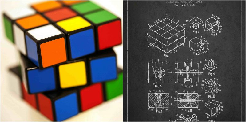
The cube was invented in 1974 by Ernő Rubik, a Hungarian architect working at the Budapest College of Applied Arts. His original goal was a structural model for teaching students about three-dimensional transformations – a physical object where the pieces could move independently but the whole would hold together. He solved that mechanical problem before he solved the puzzle itself. It reportedly took him a month to figure out how to return his own prototype to the solved state after scrambling it.
If you are curious, you will find the puzzles around you. If you are determined, you will solve them. – Ernő Rubik
The Internal Structure
From the outside, a 3x3 Rubik’s Cube looks like 27 smaller cubes arranged in a grid. There are actually only 26 visible pieces – the center of the cube is a structural core with no exposed faces. The 27th position, the geometric center, is occupied entirely by the internal mechanism.
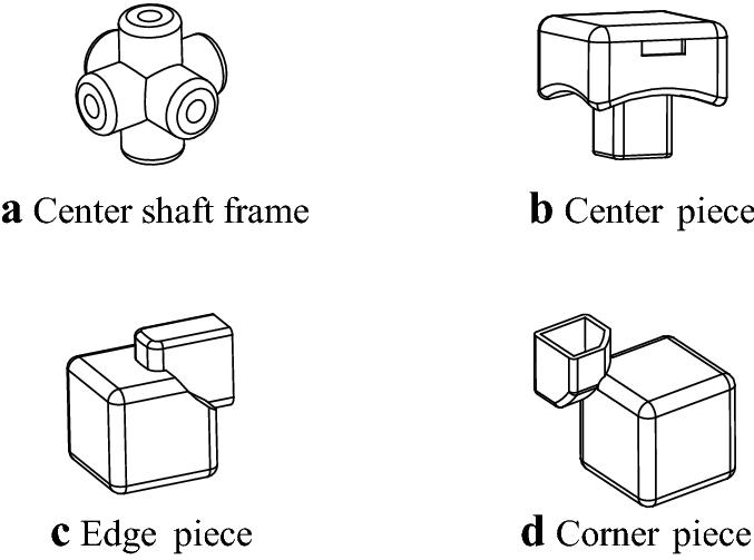
That mechanism is what makes the whole thing work. Each of the six center pieces is mounted on an arm that extends inward and connects to a central spider or core hub. The center pieces can rotate around their axis but cannot travel to a different face – no matter how many moves you make, the white center will always be opposite the yellow center, the blue opposite the green, and so on. This is not a property of the scramble; it is a property of the physical mechanism. The centers define the color of each face in the solved state.
The 12 edge pieces and 8 corner pieces interlock with each other and with the centers through a track-and-groove system. Each piece has tabs or wings that slide into curved tracks inside adjacent layers. When you rotate a face, the pieces in that face ride along the internal tracks of adjacent layers, while the core holds steady. The geometry is designed so that pieces cannot fall out during rotation but can be disassembled by turning one face 45 degrees and prying from there – a useful trick if you ever need to clean or lubricate the mechanism.
The Three Piece Types
Every piece on the cube is one of three types, and each type has a specific role in both the physical structure and the mathematical model.
Center pieces. There are six of them, one per face. Each shows one color and sits at the geometric center of its face. Centers are fixed relative to each other – they can spin in place (which matters for certain supercube variants that track sticker orientation) but cannot exchange positions. In any solver, centers define the target: you know the white face is solved when all its edge and corner neighbors have white stickers facing the white center.
Edge pieces. There are twelve, each sitting between two centers and showing exactly two colors. An edge piece has a defined solved position (the one where both its colors align with their respective center colors) and a defined orientation (it can be in that position either correctly or flipped). This concept of orientation is separate from position and becomes important in the mathematics – a misoriented edge in the right location is still wrong, and certain algorithms can move an edge without changing its orientation and vice versa.
Corner pieces. There are eight, each sitting at the intersection of three faces and showing three colors. A corner has one solved position and three possible orientations at that position (twisted 0, 120, or 240 degrees). Like edges, orientation and position are tracked independently.
The total count: 6 centers + 12 edges + 8 corners = 26 visible pieces plus the internal core.
Notation
Every solved state, scramble sequence, and algorithm in the cube world is communicated through a standard notation system. Learning it is necessary before anything else becomes readable.
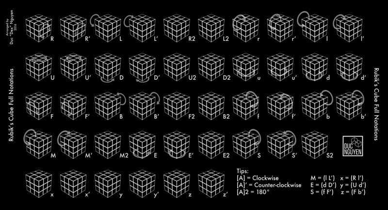
The six faces are labeled by their position relative to the solver holding the cube in a fixed orientation: U (up), D (down), F (front), B (back), R (right), L (left).
A face letter alone means a 90-degree clockwise rotation of that face when viewed from outside the cube. R rotates the right face clockwise when you look at the right side. U rotates the top face clockwise when you look down at it.
A prime symbol after the letter means counterclockwise: R’ is the right face 90 degrees counterclockwise. A 2 after the letter means 180 degrees in either direction (the result is the same): R2 rotates the right face 180 degrees.
The full set for a 3x3:
- R / R’ / R2 – right face clockwise, counterclockwise, half-turn
- L / L’ / L2 – left face
- U / U’ / U2 – top face
- D / D’ / D2 – bottom face
- F / F’ / F2 – front face
- B / B’ / B2 – back face
Algorithms are written as sequences: R U R' U' means right clockwise, then top clockwise, then right counterclockwise, then top counterclockwise. That specific sequence is called the commutator and appears in almost every beginner method. You will see it again.
There are also middle layer moves – M, E, S – for the slice between left and right, between up and down, and between front and back respectively. And whole-cube rotations – x, y, z – for reorienting the entire cube without changing the state. These come up in more advanced methods and are relevant when writing a solver that needs to reason about absolute versus relative face positions.
Color Scheme and Why It Matters
The standard Western color scheme places white opposite yellow, blue opposite green, and red opposite orange. The exact arrangement (which color is clockwise from which at each corner) follows a convention called the BOY color scheme (Blue-Orange-Yellow going counterclockwise around the white-blue-red corner). Most mass-produced cubes follow this, including official competition cubes.
This is not just cosmetic. Algorithms assume a particular spatial arrangement of colors, and when a cuber says “orient white on top with green facing you,” they are fixing the cube’s orientation in space before applying a move sequence. Solvers that take a cube state as input need to know which color belongs to which face before they can compute anything.
For a software solver, the color scheme is part of the input specification. You cannot write a state parser without knowing that white and yellow are always opposite, or that a white-blue-red corner is always in one specific physical location when solved. The physical convention feeds directly into the data representation.
What Physically Constrains the State Space
This is the connection between mechanics and mathematics that matters for building a solver.
The physical construction of the cube prevents several classes of states from ever being reached through legal moves. You cannot, for example, take a single edge piece and flip it in place while leaving everything else unchanged. The mechanism does not allow it – any sequence of moves that brings that edge back to its home position will also restore its orientation, or will have changed the orientation of at least one other edge in a compensating way. This is a parity constraint, and it comes directly from the gear-like interlocking of the piece tracks.
Similarly, you cannot take two corners and swap them without also swapping another pair of pieces somewhere else. And you cannot rotate a single corner in isolation. These are not programming rules or mathematical conventions – they are physical consequences of how the tracks work.
This means the full set of reachable cube states from the solved state is a proper subset of all mathematically conceivable arrangements of the pieces. There are 43,252,003,274,489,856,000 reachable states, which sounds enormous, but it is only 1/12 of the total number of ways you could physically rearrange the stickers if you allowed disassembly and illegal reassembly. Any solver only needs to navigate the legal portion of that space, and the constraints that define “legal” come from the mechanics described here.
Variations Worth Knowing
The 3x3 is the reference, but a few variations are relevant because they change the constraint structure in interesting ways.
2x2 (Pocket Cube). No center pieces and no edges – only 8 corners. The center position is arbitrary (you fix one corner by convention), leaving 7 corners to permute and orient. The state space is 3,674,160 – about 12 billion times smaller than the 3x3. It is a useful starting point for understanding corner orientation and permutation before adding the complexity of edges.
4x4 (Revenge). Introduces inner edge pieces that are not distinguishable by their position alone (there are two identical-looking pieces per edge slot), which creates parity issues that do not exist on the 3x3. Solving a 4x4 on the way to building an NxN solver is a good exercise precisely because of these parity edge cases.
Supercube variants. A standard 3x3 center piece can spin freely in place without affecting the puzzle, because center stickers are uniform. On a supercube, the center stickers have visible orientation (a logo, a picture, or a pattern). Suddenly center orientation matters, and the state space and constraint analysis have to account for it.
Mirror cube. Same mechanism as a 3x3, but all pieces are different sizes instead of different colors. The solved state is identified by shape (all faces flat) rather than color. Interesting because it forces you to think about what “solved” means in the absence of color information – relevant when designing a state representation that generalizes beyond the standard sticker model.
The mechanism across all of these is fundamentally the same: a central hub, face-mounted centers or equivalent, and sliding pieces constrained to move in groups. The differences are in piece count, distinguishability, and the resulting state space structure.
From Mechanics to Model
Building a solver starts here, not with algorithms or mathematics. You need to know:
- How many pieces exist and what type each is.
- What information each piece carries (position, orientation, color).
- Which constraints the physical mechanism imposes on legal states.
- What notation system maps to which physical move.
The next post works through the mathematics – how to count the state space, what group theory says about the structure of cube moves, and what properties of that structure make efficient solving possible. All of it builds on the physical model described here. A corner has three orientations because it physically has three ways to sit in its socket. An edge has two because the track geometry allows it to be either way around. Those are not mathematical definitions – they are physical facts that mathematics then describes precisely.