
DFT Scan Insertion on a NoC Router: Working Around OpenLane 2's Missing DFT Support
OpenLane 2’s Classic flow has no DFT steps. Not reduced DFT support, not a partially working implementation: none. Running Step.factory.list() against the installed package confirms it. No ScanReplace, no ScanInsert, no DFTConfig step anywhere in the openlane.steps namespace. OpenLane 1 had a run_dft flag that invoked Yosys’s dfflegalize pass followed by a Perl script to stitch chains, but none of that was ported to OpenLane 2.
This post documents how scan chain insertion was added to the flow anyway, on a 5-port wormhole NoC router targeting sky130A, using the OpenROAD DFT commands that are already present in the binary but never exposed as steps. It covers the two-step split the flow requires, the eight bugs hit along the way, the steps that had to be dropped from the Classic flow and why, and what the ATPG on the resulting netlists produced. The full physical design work on this router, including low-power runs and pipelining, is covered in the main project.
The Design
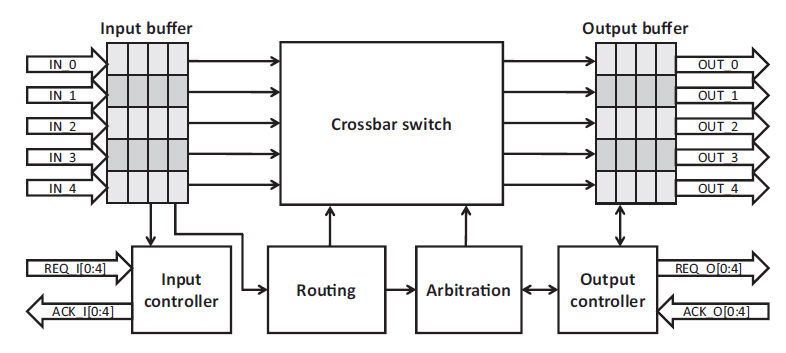
The subject is a 5-port wormhole router in Verilog targeting sky130A with sky130_fd_sc_hd. Five ports: Local, North, South, East, West. Each input port has two virtual channels, each backed by a synchronous FIFO built on a single-port SRAM macro (sram_1rw_16x16) generated by OpenRAM. 5 input ports × 2 VCs = 10 input FIFOs, plus 5 output FIFOs, giving 15 SRAM macros total. The router uses XY routing with a crossbar, switch allocator, and round-robin arbiters for contention. Flit width is 16 bits.
The DFT work ran on the pipelined version of the router: 720 flip-flops spread across the VC FIFOs, output FIFOs, state machines, and allocation logic.
Background: What Scan Insertion and ATPG Are Actually Doing
A brief explanation of what these two things accomplish and why they are separate, since they are often discussed together but address different parts of the same problem.
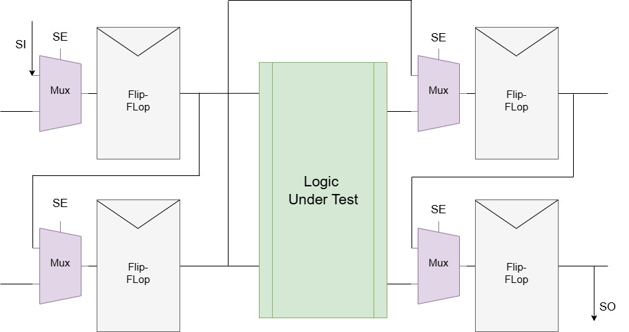
Scan chain insertion replaces every flip-flop in the design with its scan-equivalent variant. In sky130_fd_sc_hd, a DFF_X1 becomes SDFF_X1. The scan cell adds two extra ports: SCD (scan data in) and SCE (scan enable). When SCE is asserted, the flip-flop ignores its functional D input and instead captures SCD. All the scan flops are daisy-chained together by connecting each flop’s Q to the next flop’s SCD. The resulting chain is called a scan chain. To test the chip, you shift a known bit pattern through the chain (scan in), drop SCE, clock once to capture the combinational logic outputs into the flip-flops, raise SCE again, and shift everything back out (scan out) to compare against what was expected.
What this gives you is controllability and observability. Any flip-flop can be loaded with any value through the chain, and the state of any flip-flop can be read back out. A circuit that was sequential and hard to force into specific states becomes, for test purposes, a set of independent combinational cones between the scan flip-flop boundaries.
ATPG (Automatic Test Pattern Generation) determines what to shift in. Given a gate-level netlist, the ATPG tool enumerates all fault sites, which are individual gate pins and wire nodes, and for each one tries to find an input assignment that would produce a different output on a faulty chip versus a fault-free one. The fault model used here is stuck-at: a net permanently stuck at logic 0 or 1 regardless of what the driving logic computes. For each fault, the D-algorithm needs to simultaneously satisfy two conditions: activate the fault (drive the faulted node to the opposite of its stuck value) and propagate the effect to an observable output. If both conditions can be satisfied under a consistent input assignment, that assignment is a test vector. If the circuit structure makes it impossible for both to hold simultaneously, the fault is classified as structurally undetectable.
Scan insertion and ATPG are connected but separate flows. Scan insertion is a physical design operation. ATPG runs on gate-level netlists. In a complete production flow they feed into each other: the ATPG is run on the post-scan-replace netlist with the physical chain ordering from the placer taken into account, and the vectors are formatted for ATE scan load sequences. The gap between what was done here and that fully closed loop is described at the end.
Why OpenROAD Has DFT Support That OpenLane 2 Does Not Expose
OpenROAD, the PnR engine underlying OpenLane 2, has three relevant TCL commands: set_dft_config, scan_replace, and insert_dft. They work. They are in the binary bundled with OpenLane 2.3.10. The problem is that OpenLane 2 wraps OpenROAD commands into Python step classes, and none of these three were wrapped.
The only community alternative is difetto, which is distributed through Nix and is in alpha state. It conflicts with the Docker-based flow that the rest of the setup uses. It was not used here.
The path forward was to write the missing steps using the OpenLane 2 Python step API.
Why Scan Insertion Requires Two Steps at Two Different Points in the Flow
This is the structural constraint the entire implementation is built around, and it is worth explaining clearly before getting into the code.
scan_replace must run before global placement. It replaces every flip-flop instance in the netlist with its scan-equivalent. Scan cells are physically larger than the standard DFF cells they replace. In this design the sequential cell area went from 18,918 um² to 23,516 um² after scan replace, a 24% increase. If scan_replace runs after global placement, the placer has already packed the original smaller cells into the layout rows. Swapping them to larger variants creates cell overlaps that detailed placement cannot legally resolve without displacing cells by more than its allowed perturbation range. The placer needs to see the final cell sizes from the beginning.
insert_dft must run after detailed placement. It uses the physical coordinates of the already-placed scan flops to order them into minimum-wirelength chains. Running it before placement means the tool has no final location data, so chain ordering is arbitrary and scan routing wirelength is uncontrolled. The scan stitching wires it generates would also be disconnected from where the cells actually end up after placement.
CTS must come after insert_dft. The scan_enable net fans out to all 720 scan flops. If CTS runs before scan stitching, that net has no buffering and will violate max-fanout constraints across the entire design.
So the required order is:
ScanReplace → GlobalPlacement → DetailedPlacement → ScanStitch → CTS → Routing → ...
Fitting this into the Classic flow meant finding the right injection points and filtering out steps that break when the scan cells are present.
The Implementation
Two Python files: dft_step.py defining the two custom step classes, and run_dft_flow.py building the modified flow.
The Step Classes
Both classes subclass OpenROADStep. This is the correct base class for anything that generates a TCL script and runs it through the OpenROAD subprocess. The get_script_path method returns a path inside self.step_dir, the per-step directory OpenLane 2 creates fresh for each execution. The run method writes the TCL to that path and calls super().run().
ScanReplace generates:
source $::env(SCRIPTS_DIR)/openroad/common/io.tcl
read_current_odb

set_dft_config \
    -max_chains 4 \
    -clock_mixing no_mix

scan_replace

write_views
ScanStitch generates:
source $::env(SCRIPTS_DIR)/openroad/common/io.tcl
read_current_odb

insert_dft

place_pin -pin_name scan_enable_1 -layer met2 -location {0 100}  -pin_size {0.2 2}
place_pin -pin_name scan_in_1     -layer met2 -location {0 250}  -pin_size {0.2 2}
place_pin -pin_name scan_out_1    -layer met2 -location {0 400}  -pin_size {0.2 2}
place_pin -pin_name scan_in_2     -layer met2 -location {0 550}  -pin_size {0.2 2}
place_pin -pin_name scan_out_2    -layer met2 -location {0 700}  -pin_size {0.2 2}
place_pin -pin_name scan_in_3     -layer met2 -location {0 850}  -pin_size {0.2 2}
place_pin -pin_name scan_in_4     -layer met2 -location {0 1000} -pin_size {0.2 2}
place_pin -pin_name scan_out_3    -layer met2 -location {0 1150} -pin_size {0.2 2}

write_views
insert_dft reads the set_dft_config parameters stored in the ODB from the earlier scan_replace run, builds the chains using the flop coordinates from detailed placement, and creates the scan ports in the ODB. It names them scan_in_N, scan_out_N, and scan_enable_N automatically. The place_pin calls put those ports on met2 on the left edge of the die, spaced 150 um apart. The die is 1358 x 1369 um so all eight ports fit within the boundary.
The config variables (DFT_MAX_CHAINS, DFT_MAX_LENGTH, DFT_CLOCK_MIXING) are declared as Variable instances on each class so OpenLane 2 can read them from config.json. no_mix for clock mixing means the tool will not interleave flops from different clock domains into the same chain.
The Flow Builder
run_dft_flow.py pulls the standard Classic step list, finds the indices of OpenROAD.GlobalPlacement and OpenROAD.DetailedPlacement, and splices in the two custom steps:
steps = steps[:gpl_idx] + [ScanReplace] + steps[gpl_idx:dpl_idx+1] + [ScanStitch] + steps[dpl_idx+1:]
Three Classic steps were removed before building the modified list.
OpenROAD.RepairDesignPostGPL runs buffer insertion and cell resizing after global placement to fix slew and cap violations. After scan replace, the SDC timing constraints include transition time checks on the new SCD and SCE ports, which have no set_max_transition constraints in the original SDC. The repair step produces an unrecoverable error about unconstrained transition paths on those ports. Removing it is safe because post-GPL repair is a timing optimization, not a placement correctness requirement. The slew and cap violations it would have addressed still exist in the final signoff report, but they are pre-existing across all runs in this project and attributed to the SRAM macro output driver characteristics, not to the removal of this step.
Odb.CheckDesignAntennaProperties checks antenna ratios on the post-route netlist. Magic’s LEF writer, when processing scan ports created by OpenROAD, emits USE ; with no value for the scan port type. The correct LEF syntax is USE SCAN ;. The ODB LEF parser aborts with a SIGABRT on the empty USE value. The GDS is written at step 58 (Magic.StreamOut) before this step runs, so removing it loses only the antenna check, not the GDS or the ODB.
Yosys.EQY runs formal equivalence checking between the original RTL and the post-PnR gate netlist. After scan replace, every flip-flop in the netlist has SCD and SCE ports that do not exist on the original RTL DFF instances. The equivalence checker sees mismatched module interfaces and fails immediately. A DFT-aware equivalence flow would check only the functional behavior in non-scan mode, which requires a separate EQY configuration. That is outside the scope of this work, so the step was dropped.
The flow also re-launches itself inside the OpenLane 2 Docker container if it detects it is running outside one, using the same run_in_container mechanism that the standard OpenLane CLI uses.
The Bugs
Eight distinct bugs were hit getting from a first attempt to a working 75/75 stage run.
Bug 1: CURRENT_ODB is not defined. The first TCL attempt loaded the database with read_db $::env(CURRENT_ODB). This fails because CURRENT_ODB is not set in the subprocess environment when OpenROADStep launches OpenROAD. The OpenLane 2 source uses io.tcl to handle this. Sourcing that file and calling read_current_odb works because io.tcl reads the ODB path through a mechanism that OpenLane 2 does populate. read_db $::env(CURRENT_ODB) cannot work by design.
Bug 2: Wrong TCL command name for scan stitching. The command is insert_dft, not execute_dft_plan. OpenROAD documentation across versions is inconsistent on this. execute_dft_plan does not exist and produces invalid command name "execute_dft_plan" from the TCL interpreter.
Bug 3: Python template marker in TCL. An earlier version of the ScanStitch TCL included %OL_CREATE_REPORT to trigger OpenLane 2’s report generation hook. This is a Python-side substitution marker that gets processed before the TCL is sent to OpenROAD. When it is not substituted (because the mechanism works differently in a custom step), OpenROAD sees raw %OL_CREATE_REPORT as TCL and produces a parse error. write_views handles output serialization correctly without any custom report hook.
Bug 4: RepairDesignPostGPL failing on unconstrained scan ports. This is the step removal described above. The error presents as a hard failure with a stack trace about transition time constraints, and it produces no output ODB, so the flow cannot continue. The only fix is removing the step from the flow before the run starts.
Bug 5: ScanReplace running after GlobalPlacement causes DetailedPlacement to fail. The first working build of the flow injected ScanReplace after GlobalPlacement, which seemed like the natural place to put a netlist-modifying step that doesn’t involve placement. The detailed placer then received a netlist where cells had been swapped to larger scan variants but the placement coordinates were from the pre-swap smaller cells. The resulting overlaps were not resolvable within the legal perturbation range. The DEF had cells physically intersecting each other. Moving ScanReplace to before GlobalPlacement gives the placer the correct cell sizes from the start.
Bug 6: Scan output pins silently dropped due to wrong coordinate units. After the first run that reached routing, global routing failed with [GRT-0209] Pin scan_out_3 is completely outside the die area and cannot be routed. Looking at the DEF after CTS showed all scan_in_* pins with FIXED status but all scan_out_* pins missing entirely. The original place_pin calls used what looked like reasonable coordinates: {0 1150000}. The problem is that place_pin in OpenROAD expects coordinates in microns, not database units. 1150000 is 1.15 meters, which is outside the 1358 um die by three orders of magnitude. OpenROAD did not produce an error for out-of-bounds output pins; it dropped them silently. Input pins appear to have been placed at the nearest legal location due to DBU rounding at extreme values, which is why the scan_in_* pins showed up with status FIXED while the output pins disappeared. Dividing all coordinate values by 1000 to convert from DBU to microns fixed it. After that change, all eight scan ports appeared with FIXED status in the DEF.
Bug 7: Magic’s LEF writer emitting invalid USE syntax for scan ports. After routing completed and GDS was written, the flow reached Odb.CheckDesignAntennaProperties and crashed with a SIGABRT. The Magic-generated LEF for the design contained:
PIN scan_enable_1
  DIRECTION INPUT ;
  USE  ;
The correct LEF syntax is USE SCAN ;. Magic’s LEF writer does not know how to emit the SCAN use type for ports created by OpenROAD’s DFT flow. The ODB LEF parser aborts on the empty value. Since the GDS was already written by Magic.StreamOut at step 58 before this step runs, removing Odb.CheckDesignAntennaProperties from the flow loses only the antenna check.
Bug 8: flow.start() return value unpacking. After all the above were fixed, the flow completed all 75 stages but Python threw ValueError: too many values to unpack (expected 2) on state, steps = flow.start(tag="pipe_dft"). The version of SequentialFlow.start() in the installed OpenLane 2 returns a tuple with more than two elements. The fix was replacing the unpacking assignment with a bare flow.start(tag="pipe_dft") call, since neither return value was used anywhere in the script.
Results
The flow completed 75 of 75 stages. LVS passed. The output covers DEF, GDS, netlist, ODB, SDF, SPEF, and the full set of signoff outputs.
720 flip-flops were replaced with scan-equivalent SDFF cells. OpenROAD built 4 scan chains and created 8 scan ports: scan_in_1 through scan_in_4, scan_out_1 through scan_out_3, and scan_enable_1. All eight are on met2 on the left edge of the die.
The DRC report shows 132 nwell.4 violations. Every one of them is inside an SRAM macro instance boundary. Zero routing DRC violations exist on the standard cell or interconnect layers. This is a known limitation of OpenRAM-generated macros on sky130 under Magic DRC. The nwell.4 rule checks that every nwell region has a metal-connected N+ tap within a specified distance. The abstract LEF used during PnR exposes only the metal interface of each macro, not the internal tap cell geometry that satisfies the rule. Magic sees the nwell regions from the macro boundary without the internal taps. These violations are identical across every run in this project, including the unmodified baseline, and are documented in the official OpenLane and SkyWater PDK known issues pages.
Impact of Scan Cell Replacement on the Design
Swapping every DFF for its SDFF equivalent has a measurable cost. The scan cells are physically larger because of the additional SCD and SCE ports and the internal mux that selects between the functional D and the scan SCD input.
| Metric | Before scan replace | After scan replace |
|---|---|---|
| Sequential cell area (um²) | 18,918 | 23,516 |
| Sequential cell area increase | +24.3% | |
| Flip-flops | 720 | 720 |
| Scan chains | 0 | 4 |
| Scan ports | 0 | 8 (on met2, left edge) |
| Flow stages completed | 75 / 75 | 75 / 75 |
| LVS | Pass | Pass |
| Routing DRC violations | 0 | 0 |
The 24% increase in sequential cell area is entirely from the cell swap. The total standard cell area change is smaller in percentage terms because the sequential cells are a subset of the full cell count. The rest of the design, combinational logic, buffers, and the SRAM macros, is unchanged. Routing DRC stays clean at zero because the scan chains are routed by the standard GRT/DRT passes using the same metal stack as everything else.
The 4 scan chains covering 720 flops give 180 flops per chain on average. The physical chain ordering is determined by insert_dft using the flop coordinates from detailed placement, grouping spatially adjacent flops to minimize scan routing wirelength.
ATPG Using the Post-PnR Netlist
scan_replace runs on the ODB at the netlist stage, before global placement. It modifies the netlist in-place inside the database, swapping every DFF* to its SDFF* equivalent, and writes it back out via write_views. Placement and routing then happen on that modified netlist. The final Verilog netlist in runs/pipe_dft/final/ is the post-scan-replace gate netlist: SDFFs with SCD and SCE ports wired into the 4 chains, all routed.
This is the correct netlist to run ATPG against. Earlier in the project ATPG was run on independently synthesized submodule netlists using Fault’s own internal Yosys, which is a separate synthesis pass with no connection to the OpenLane flow output. Using the final post-PnR netlist instead means the ATPG is running on the exact same netlist that LVS verified against the GDS.
The flow is the same as any Fault run: pass the final netlist through fault synth with the sky130 cell models, run fault cut to sever D-Q on every flop and produce a combinational netlist with pseudo-primary I/O at each flop boundary, then run the D-algorithm ATPG against the cut netlist. Fault’s cut step has no knowledge of scan chain topology; it treats every flop boundary as independently controllable and observable. This is valid because the physical scan chains do provide exactly that controllability, serially, through the shift operation.
ATPG was run on four submodules from the final post-PnR netlist: rr_arbiter, switch_allocator, vc_fifo, and input_unit. Running on the full top-level netlist is not feasible because Fault spawns one Icarus simulation process per test vector application, and at 34,900 fault sites across the full design the parallel processes exhaust available RAM. The four submodules cover all sequential logic in the design; the crossbar is purely combinational and was omitted.
| Module | Fault Coverage | Runtime |
|---|---|---|
| rr_arbiter | 96.43% | 5.00s |
| switch_allocator | 95.46% | 7.12s |
| vc_fifo | 98.09% | 10.60s |
| input_unit | 96.59% | 17.22s |
All four exceeded 95%. The remaining uncovered faults are structurally undetectable: fault sites where the circuit topology itself prevents simultaneous fault activation and propagation to any observable output, typically through reconvergent fanout or redundant priority decode logic in the arbiters. Generating more vectors does not help; the limit is structural.
One gap remains. Fault produces vectors under the full-scan assumption: arbitrary independent controllability of every flop. The physical scan chains in the design do provide that, but serially through the shift sequence. Fault does not produce ATE-formatted vectors that account for which flop sits at position N in chain K. Getting from the coverage numbers here to an actual scan load/capture/unload sequence for silicon testing requires mapping the vectors to the chain ordering that insert_dft produced. That mapping was not done.