

Building a Hardware Scan-Line Triangle Rasterizer: From Single-Pixel Core to SIMD Warp Architecture
Pre-shader fixed-function rasterization architectures are well-documented at the block-diagram level but seldom implemented from scratch outside of academic or driver-development contexts. The canonical examples are the SGI RealityEngine (1993) and the NVIDIA NV1 (1995), both of which implemented rasterization as a fixed sequence of hardwired datapath stages: edge setup, scan conversion, interpolation, and pixel write. The design constraint they shared was that every stage had to be throughput-bounded by a simple worst-case formula, with no general-purpose programmable logic in the hot path.
This post documents the construction of a synthesisable SystemVerilog implementation of that fixed-function datapath, with a SIMD parallel execution model built directly on top of it. The baseline implements the standard single-pixel-per-cycle scan walk with correct fixed-point arithmetic and no floating-point anywhere in the RTL. The SIMD variant extends this to a warp-based architecture: the rasterizer outputs N pixels per cycle as a masked warp, a warp FIFO absorbs burst output, and a set of parallel interpolation and shading lanes process all N pixels simultaneously before a single-cycle coalesced framebuffer write. The core arithmetic and the validation infrastructure are shared between both. This post documents the construction of both, and the iteration required to get from a first working SIMD attempt to a clean design.
TL;DR
The implementation is a synthesisable fixed-function scan-line triangle rasteriser in SystemVerilog, with a SIMD parallel variant built on top of the same arithmetic core. The entire pipeline from vertex input to framebuffer write runs on signed fixed-point integers with no floating-point anywhere in the RTL, and no programmable shader stages. The datapath is hardwired: edge setup computes the three half-plane coefficients and signed area, scan conversion walks the bounding box with incremental addition only, barycentric interpolation weights the per-vertex colour attributes, Gouraud shading blends them, and the result is written to the framebuffer.
The scalar baseline produces one pixel per cycle. The SIMD variant extends the rasterizer with an OUT_W=8 parameter, evaluating 8 horizontally adjacent pixels simultaneously per cycle using a combinational generate loop over the row-start accumulators. Output is a masked warp of 8 pixels that passes through a warp FIFO, 8 parallel interpolation and shading lanes, and a single-cycle coalesced write across 8 independent framebuffer ports.
| Scene | Triangles | Pixels | Scalar (cycles) | SIMD (cycles) | Speedup |
|---|---|---|---|---|---|
| Hello Triangle | 1 | 25,313 | 50,670 | 6,580 | 7.7x |
| Quads | 8 | 63,000 | 125,220 | 16,300 | 7.7x |
| Sunset | 20 | 72,752 | 146,736 | 19,426 | 7.6x |
Scalar throughput is 0.50 px/cyc across all three scenes, consistent with the one-pixel-per-cycle scan walk. SIMD throughput is 3.85 px/cyc (hello triangle), 3.87 px/cyc (quads), and 3.75 px/cyc (sunset). Large axis-aligned triangles with dense horizontal coverage reach 3.89 to 3.93 px/cyc, approaching the theoretical ceiling of 4.0 px/cyc at 50% fill efficiency for warp size 8. The sunset’s small triangles (157 to 160 pixels each) pull the average down due to partial-warp overhead at row ends. Rasterizer backpressure is zero across all three SIMD runs; the warp FIFO depth of 16 is sufficient to absorb burst output without stalling the scan walk.
The rasteriser accepts a flat list of screen-space triangles with per-vertex colour attributes and renders them directly. Static scenes are passed as-is. For 3D animated content, a preprocessing step handles the model transform, view transform, and perspective projection per frame, outputting a flattened list of projected 2D triangles that the rasteriser consumes identically to any other input. The hardware has no knowledge of 3D coordinates, cameras, or animation state; all of that is resolved before the triangle list is handed off.
The Mathematics
Every rasterization decision in this design reduces to integer arithmetic evaluated at fixed-point coordinates. There is no floating-point anywhere in the RTL; the entire chain from vertex input to framebuffer write runs on signed fixed-point integers. The SIMD datapath builds directly on this arithmetic foundation; none of what follows changes when the parallel variant is introduced.
Edge equations. A triangle with screen-space vertices $v_0, v_1, v_2$ defines three half-plane tests. For edge $i \to j$, the edge equation evaluated at a pixel $(x, y)$ is:
$$E_{ij}(x, y) = (v_{iy} - v_{jy})\,x + (v_{jx} - v_{ix})\,y + (v_{ix}\,v_{jy} - v_{jx}\,v_{iy})$$or more compactly $E_{ij}(x,y) = A_{ij}\,x + B_{ij}\,y + C_{ij}$, where:
$$A_{ij} = v_{iy} - v_{jy}, \quad B_{ij} = v_{jx} - v_{ix}, \quad C_{ij} = v_{ix}\,v_{jy} - v_{jx}\,v_{iy}$$A pixel is inside the triangle if and only if all three edge evaluations are non-negative simultaneously:
$$E_{01}(x,y) \ge 0 \;\wedge\; E_{12}(x,y) \ge 0 \;\wedge\; E_{20}(x,y) \ge 0$$This is the RTL coverage test: wire covered = (e01 >= 0) && (e12 >= 0) && (e20 >= 0);

Signed area and winding. The $C$ terms are cross products of vertex pairs. Summing them gives twice the signed area of the triangle:
$$2 \cdot \text{area} = (v_{1x} - v_{0x})(v_{2y} - v_{0y}) - (v_{2x} - v_{0x})(v_{1y} - v_{0y})$$The RTL computes this as area2. If area2 < 0, the winding is clockwise in screen space and all three edge equations are negated before the scan walk so the coverage test holds regardless of input winding convention. Degenerate triangles (area2 == 0) are silently dropped in the LOAD state.
Bit-width discipline. Vertex coordinates are 16-bit signed integers. The $A$ and $B$ coefficients are differences of 16-bit values, fitting in 17 bits. The $C$ coefficient is a product of two 16-bit values, requiring 32 bits. The SX macro sign-extends a 16-bit coordinate to 32 bits before any multiply:
`define SX(x) {{(32-SW){x[SW-1]}}, x}
Without this, the cross products in $C_{ij}$ overflow on large triangles. All coefficients are declared signed [31:0]. edge_setup uses SX in every coefficient computation: all six terms for all three edges, plus the area:
A01 <= `SX(v0y) - `SX(v1y);
B01 <= `SX(v1x) - `SX(v0x);
C01 <= `SX(v0x)*`SX(v1y) - `SX(v1x)*`SX(v0y);

area2 <= (`SX(v1x)-`SX(v0x))*(`SX(v2y)-`SX(v0y))
        -(`SX(v2x)-`SX(v0x))*(`SX(v1y)-`SX(v0y));
The rasterizer uses SX32 (a rename of the same macro) when evaluating the initial edge values at (minx, miny) in the LOAD state. The distinction matters: edge_setup signs from SW-bit to 32-bit at the point of compute; the rasterizer re-signs the bounding box coordinates again when seeding the walker, because those values arrive as SW-bit integers and must be widened before the multiply with the 32-bit coefficients.
Incremental edge evaluation. Evaluating $E_{ij}(x,y) = A_{ij}\,x + B_{ij}\,y + C_{ij}$ per pixel with full multiplies would be expensive. The scan walker exploits the linearity: stepping one pixel right adds $A_{ij}$ to the current value, stepping one row down adds $B_{ij}$:
$$E_{ij}(x+1,\, y) = E_{ij}(x,y) + A_{ij}$$$$E_{ij}(x,\, y+1) = E_{ij}(x,y) + B_{ij}$$So the rasterizer computes $E_{ij}(\text{minx}, \text{miny})$ once at triangle load (one multiply per edge), then walks the bounding box with only additions. No multiplies in the inner loop. The SCAN state implements this directly: on a horizontal step cx increments and each accumulator adds its A; when the row ends the row-start trackers e01r/e12r/e20r each add their B and the pixel accumulators are reset from the updated row-start values:
if (cx == rMaxx) begin
    cx <= rMinx;
    if (cy == rMaxy) begin
        st <= EMIT_DONE;
    end else begin
        cy   <= cy + 1;
        e01r <= e01r + rB01;  e12r <= e12r + rB12;  e20r <= e20r + rB20;
        e01  <= e01r + rB01;  e12  <= e12r + rB12;  e20  <= e20r + rB20;
    end
end else begin
    cx  <= cx + 1;
    e01 <= e01 + rA01;  e12 <= e12 + rA12;  e20 <= e20 + rA20;
end
The row-start trackers are necessary because the pixel accumulators drift across the row; you cannot add B to e01 at row end because it already holds E01(maxx, cy), not E01(minx, cy). The separate e01r holds E01(minx, cy) updated once per row, which is the correct base for the next row.
Barycentric weights. When a pixel is covered, its barycentric coordinates $w_0, w_1, w_2$ with respect to the three vertices are the edge equation values themselves; they are proportional to the sub-triangle areas opposite each vertex:
$$w_0 = E_{12}(x,y), \quad w_1 = E_{20}(x,y), \quad w_2 = E_{01}(x,y)$$These are already computed as part of the coverage test, so they are forwarded to the interpolator at zero additional cost. The assignment looks inverted at first glance, $w_0$ is e12, not e01, but this is correct: $E_{12}$ is zero on edge $v_1 v_2$ and grows toward $v_0$, making it the weight for vertex 0. The rasterizer forwards them as:
out_w0 <= e12;  // weight for v0 — proportional to distance from edge 1-2
out_w1 <= e20;  // weight for v1 — proportional to distance from edge 2-0
out_w2 <= e01;  // weight for v2 — proportional to distance from edge 0-1
Color interpolation. Gouraud shading computes per-pixel color as a weighted blend of the three vertex colors normalized by area2. For each channel $c \in \{R, G, B\}$:
The numerator is accumulated in a 48-bit signed intermediate to avoid overflow ($32\text{-bit weight} \times 8\text{-bit color} \times 3$). The division by area2 is the only divide in the entire datapath, and it runs once per covered pixel in the interpolator’s second stage. The result is clamped to $[0, 255]$ before writing to the framebuffer.
The interpolator is a two-stage registered pipeline. Stage 1 computes the weighted sums, zero-extending the 8-bit colors to avoid sign errors in the multiply:
// Stage 1 — weighted sum, zero-extend colours to 48 bits
s1r <= in_w0*{{40{1'b0}},v0r} + in_w1*{{40{1'b0}},v1r} + in_w2*{{40{1'b0}},v2r};
s1g <= in_w0*{{40{1'b0}},v0g} + in_w1*{{40{1'b0}},v1g} + in_w2*{{40{1'b0}},v2g};
s1b <= in_w0*{{40{1'b0}},v0b} + in_w1*{{40{1'b0}},v1b} + in_w2*{{40{1'b0}},v2b};
Stage 2 divides by area2 and clamps. The divc function handles the divide-by-zero edge case and the $[0,255]$ clamp in one call:
function automatic [7:0] divc(input signed [47:0] n, input signed [31:0] d);
    logic signed [47:0] q;
    if (d == 0) return 8'd0;
    q = n / d;
    if (q < 0)   return 8'd0;
    if (q > 255) return 8'd255;
    return q[7:0];
endfunction
Colors are zero-extended rather than sign-extended because they are unsigned quantities. If the 8-bit color were sign-extended into the 48-bit multiply, a color value of 0xFF would be treated as $-1$ rather than $255$, producing wrong interpolation near white. This is a common correctness trap when mixing signed and unsigned arithmetic in wide multiplies.
RTL Practices
Several structural decisions in the RTL are worth calling out because they are non-obvious from the architecture description alone. These practices apply uniformly across both variants, baseline and SIMD, since they share the same foundational modules and extend rather than replace them.
default_nettype none is declared at the top of every module. This makes undeclared net references a compile error rather than an implicit one-bit wire, which is how implicit-net bugs survive into simulation undetected.
Valid/ready handshake throughout. Every inter-module boundary uses out_valid / in_ready flow control. The rasterizer is the only stage that can stall; it asserts backpressure when the downstream FIFO is full. Edge setup is always ready (single-cycle registered output). The interpolator is a fixed two-stage register chain with no stall logic; the FIFO in front of it absorbs any rate mismatch. In the SIMD variant there is a single warp FIFO between the rasterizer and the interpolator, and out_ready to the rasterizer is !warp_fifo_full.
Winding normalization at load time. The LOAD state in the rasterizer checks area2 < 0 and negates all six $A$ and $B$ coefficients along with the three $C$ terms before beginning the scan. This means the SCAN state’s coverage test is always >= 0 with no branch. One conditional at triangle start, zero conditionals per pixel. This holds identically in the SIMD rasterizer, the negation happens once at LOAD and all four lane accumulators are seeded from the already-normalised coefficients.
The sign check uses area2[31], testing the MSB directly rather than area2 < 0, which synthesises to a single wire rather than a comparator. Both forms are correct for two’s-complement signed integers; the bit-select is marginally cleaner in RTL:
if (area2[31]) begin  // area2 < 0 → CW winding
    rA01 <= -A01;  rB01 <= -B01;
    rA12 <= -A12;  rB12 <= -B12;
    rA20 <= -A20;  rB20 <= -B20;
    rArea2 <= -area2;
    e01r <= -eval01_init;  e12r <= -eval12_init;  e20r <= -eval20_init;
    e01  <= -eval01_init;  e12  <= -eval12_init;  e20  <= -eval20_init;
end else begin
    rA01 <= A01;  rB01 <= B01;
    // ... positive path unchanged
end
eval01_init is a combinational wire that evaluates $E_{01}(\text{minx}, \text{miny})$ using the incoming (not-yet-negated) coefficients. Negating it in the same if block ensures the initial accumulator value is consistent with the negated rA/rB values the SCAN loop will use.
Sign extension as a named macro. Rather than relying on SystemVerilog’s implicit sign-extension rules (which vary with operator context), every coordinate widening is done through the explicit SX / SX32 macro. This makes the intent visible at the call site and prevents silent truncation when mixing signed and unsigned operands. The SIMD rasterizer uses SX32 identically for the initial edge evaluation at (minx, miny).
Flattened port arrays for Icarus compatibility. SystemVerilog packed arrays cannot be passed through module ports in all Icarus Verilog versions. The SIMD rasterizer works around this by flattening per-lane outputs into wide single-dimension vectors, out_px is [OUT_W*SW-1:0] carrying all N X coordinates packed, out_w0 is [OUT_W*32-1:0], and downstream modules slice them with hardcoded bit ranges. No +: indexed part-selects are used in port connections for the same reason.
Fragment FIFO design. frag_fifo is a synchronous FIFO with registered read output (one-cycle latency after pop). Full and empty are detected using the extra-MSB pointer trick: the write and read pointers each carry one extra bit beyond the address width. When the extra bits differ but the lower bits match, the FIFO is full; when the pointers are equal it is empty. This avoids a separate counter and synthesises to a small comparator:
localparam PTR = $clog2(DEPTH);
logic [PTR:0] wr_ptr, rd_ptr;  // extra MSB for full/empty

assign full  = (wr_ptr[PTR] != rd_ptr[PTR]) &&
               (wr_ptr[PTR-1:0] == rd_ptr[PTR-1:0]);
assign empty = (wr_ptr == rd_ptr);
The FIFO depth of 16 is the rate-match buffer between the rasterizer (bursty, may emit one warp every cycle across a dense triangle) and the interpolator (fixed two-cycle latency with no stall). A depth of 16 provides enough slack that the rasterizer rarely stalls even on full-screen triangles.
Module replication over parameterised arrays. The SIMD gpu_top instantiates the replicated simd_interp and simd_pixel_shader modules explicitly rather than using generate loops over arrays. This is an Icarus compatibility choice, generate loops over module arrays with individually-named signals are unreliable in older iverilog. Each instance is wired explicitly, which is verbose but unambiguous.
Degenerate triangle handling. The rasterizer checks area2 == 0 in LOAD and pulses done immediately without entering SCAN. This prevents the walker from hanging on collinear input, which would otherwise spin indefinitely with no covered pixels. Both the single-lane and SIMD rasterizers implement this identically.
The done pulse is load-bearing beyond its obvious role: cmd_proc holds tri_valid until it sees done, so a missing pulse stalls the entire command interface permanently. Degenerate triangles must pulse done even though no pixels were emitted:
LOAD: begin
    if (area2 == 32'sd0) begin
        busy <= 0;
        done <= 1;   // must pulse done so cmd_proc can accept the next command
        st   <= IDLE;
    end else begin
        // ... normal load
        st <= SCAN;
    end
end
Command word encoding. cmd_proc decodes 32-bit packets where the top 4 bits are the opcode. Opcodes 0x1–0x7 are the baseline triangle path (three vertex positions, three vertex colors, draw). Fog opcodes 0x8–0xC (framebuffer clear, fog enable, fog color, fog center, fog near/range) are broadcast to all shader instances simultaneously.
The full opcode map as decoded in cmd_proc:
0x1  v0 position  [27:14]=x  [13:0]=y   (signed 14-bit)
0x2  v1 position  [27:14]=x  [13:0]=y
0x3  v2 position  [27:14]=x  [13:0]=y
0x4  v0 color     [23:16]=R  [15:8]=G   [7:0]=B
0x5  v1 color
0x6  v2 color
0x7  DRAW         (fires tri_valid)
0x8  FB_CLEAR     (clears framebuffer)
0x9  FOG_EN       [0]=enable
0xA  FOG_COLOR    [23:16]=R  [15:8]=G   [7:0]=B
0xB  FOG_CENTER   [27:14]=cx [13:0]=cy
0xC  FOG_RANGE    [27:14]=near [13:0]=range
Seven commands per triangle. cmd_ready is wired directly to tri_ready, meaning the entire command interface stalls whenever the rasterizer is busy with a triangle. No command buffering exists; the testbench must respect backpressure.
A static triangle smoke test reveals very little. A single correctly-rendered triangle is consistent with a correct hardware chain and equally consistent with an implementation that happens to produce the right output for one degenerate input. What exposes bugs is geometry that exercises every code path simultaneously: backface culling, winding normalization, perspective-correct projection, depth sort, and multiple independent object transforms. A rotating 3x3 Rubik’s cube with a layer-by-layer solve animation hits all of those. Getting there took longer than expected.
The Hardware
The hardware is a handshake-connected chain of synthesisable SystemVerilog modules running in simulation under Icarus Verilog. Two variants of this chain exist: the baseline single-pixel-per-cycle build, and the SIMD build. Both share cmd_proc, edge_setup, frag_fifo, and framebuffer unchanged. The SIMD variant adds simd_interp, simd_pixel_shader, writeback_coalescer, and framebuffer_mp, and the rasterizer gains an OUT_W parameter that controls the lane count.
Baseline datapath. Command words arrive at the front end as 32-bit packets over a valid/ready interface. The top four bits are the opcode. Six opcodes load vertex positions and colors into internal registers; a seventh fires the draw. Seven commands per triangle, no internal buffering, backpressure from any downstream stage propagates immediately to the command interface.
Command Processor and Opcode Structure
All communication between the testbench (or any upstream host) and the hardware runs over a single 32-bit valid/ready channel into cmd_proc. Every transaction is one word. The top 4 bits [31:28] are the opcode; the remaining 28 bits carry the payload, packed differently per opcode. There is no handshake beyond cmd_valid / cmd_ready; the command is consumed on the cycle both are high.
cmd_ready is wired directly to tri_ready:
assign cmd_ready = tri_ready;
This means the entire command interface stalls whenever the rasterizer is busy processing a triangle. The testbench cannot send the next triangle’s vertex words until the current triangle is fully rasterised and done pulses. No command buffering exists anywhere in the design.
2D triangle commands. A complete 2D triangle requires exactly seven consecutive command words:
Word 1  opcode 0x1  [27:14]=v0x  [13:0]=v0y   (signed 14-bit screen coords)
Word 2  opcode 0x2  [27:14]=v1x  [13:0]=v1y
Word 3  opcode 0x3  [27:14]=v2x  [13:0]=v2y
Word 4  opcode 0x4  [23:16]=R  [15:8]=G  [7:0]=B   (v0 color)
Word 5  opcode 0x5  v1 color
Word 6  opcode 0x6  v2 color
Word 7  opcode 0x7  DRAW — fires tri_valid

The position and color opcodes (0x1–0x6) write into holding registers inside cmd_proc. Opcode 0x7 pulses tri_valid combinationally from those registers. Order within the position and color groups does not matter (each opcode writes to its own named register), but 0x7 must come last. cmd_proc in always_ff implements this as a straightforward case statement with no sequencing FSM:
case (cmd_data[31:28])
    4'h1: begin r_v0x <= $signed(cmd_data[27:14]);
                r_v0y <= $signed(cmd_data[13:0]);  end
    4'h2: begin r_v1x <= ...  end
    4'h3: begin r_v2x <= ...  end
    4'h4: begin r_v0r <= cmd_data[23:16]; r_v0g <= cmd_data[15:8];
                r_v0b <= cmd_data[7:0];  end
    // ...
    4'h7: tri_valid <= 1;
Framebuffer and fog commands. The framebuffer clear and fog configuration are single-word commands that take effect on the cycle they arrive, with no acknowledgement:
0x8  FB_CLEAR    — pulses fb_clear; both framebuffer and depth buffer begin sequential clear
0x9  FOG_ENABLE  [0]=1 to enable, 0 to disable
0xA  FOG_COLOR   [23:16]=R  [15:8]=G  [7:0]=B
0xB  FOG_CENTER  [27:14]=cx  [13:0]=cy   (pixel coordinates)
0xC  FOG_RANGE   [27:14]=near  [13:0]=range   (pixel distances)
Fog parameters are registered in cmd_proc and held until updated. They are broadcast identically to all pixel_shader instances; no per-lane fog state exists.
3D pipeline commands. The 3D path requires loading the transform configuration before issuing vertex data. The transform coefficients use a sub-opcode scheme within opcode 0xE: bits [27:24] select which coefficient to update, and bits [23:8] carry the 16-bit Q1.14 or Q6.6 value:
0xE sub 0  vs_sin_y    Q1.14  (sin of Y rotation angle × 16384)
0xE sub 1  vs_cos_y    Q1.14
0xE sub 2  vs_sin_x    Q1.14
0xE sub 3  vs_cos_x    Q1.14
0xE sub 4  vs_sin_z    Q1.14
0xE sub 5  vs_cos_z    Q1.14
0xE sub 6  vs_scale_q6 Q6.6   (scale factor × 64; 64 = 1.0×)
0xE sub 7  vs_fov_q6   Q6.6   (field of view × 64; 300 → 19200)
0xE sub 8  vs_cam_z_q6 Q6.6   (camera Z offset × 64; 200 → 12800)
0xF        vs_trans_x/y        [27:14]=tx  [13:0]=ty  (screen-space translate)
After the nine 0xE words and one 0xF, vertex data arrives as 0xD words. Each 0xD word carries one 3D vertex, signed 9-bit per axis, packed into 27 bits:
0xD [26:18]=x [17:9]=y [8:0]=z (signed 9-bit each, raw integer coords)
The color for the 3D vertex is taken from whichever v0 color was last loaded via 0x4. Three consecutive 0xD words complete one triangle, which prim_assembly assembles, culls, projects, and fires into the same edge_setup → rasterizer path that 2D triangles use.
The reset defaults in cmd_proc are: scale=64 (1.0×), all sin=0, all cos=16384 (1.0 in Q1.14), fov=19200 (300×64), cam_z=12800 (200×64), translate=(128,128). A freshly reset design renders 3D geometry with a standard perspective projection centered at (128,128) without any pre-configuration.
From the command front end, the triangle passes to edge_setup, which computes three edge equations of the form E(x,y) = Ax + By + C from the three screen-space vertices, along with the bounding box and signed 2× triangle area. Single clock cycle, always ready. The sign-extension macro widening 16-bit coordinates to 32 bits before multiply is load-bearing: without it the cross products overflow on large triangles.
A01 <= `SX(v0y) - `SX(v1y);
B01 <= `SX(v1x) - `SX(v0x);
C01 <= `SX(v0x)*`SX(v1y) - `SX(v1x)*`SX(v0y);

area2 <= (`SX(v1x)-`SX(v0x))*(`SX(v2y)-`SX(v0y))
        -(`SX(v2x)-`SX(v0x))*(`SX(v1y)-`SX(v0y));
The bounding box is clamped to [0, SCR_W-1] × [0, SCR_H-1] before being handed to the rasterizer. This is not just a bounds check on output; it is a necessary rasterizer correctness measure. Without clamping, a triangle that partially overlaps the screen edge would give the rasterizer minx < 0, and the incremental walker would spend cycles on pixels that the framebuffer write would silently drop, with correct but wasteful behavior. With clamping, the walker only visits pixels that will actually be written:
minx <= sclamp(smin3(v0x, v1x, v2x), SW'(0), SW'(SCR_W-1));
miny <= sclamp(smin3(v0y, v1y, v2y), SW'(0), SW'(SCR_H-1));
maxx <= sclamp(smax3(v0x, v1x, v2x), SW'(0), SW'(SCR_W-1));
maxy <= sclamp(smax3(v0y, v1y, v2y), SW'(0), SW'(SCR_H-1));
The rasterizer walks every pixel in the bounding box incrementally: add $A$ per horizontal step, add $B$ per row. No multiply per pixel, only additions. Pixels where all three edge values are non-negative are covered. Winding is resolved at load time by checking the sign of area2 and negating all three edge equations if it is negative, so the coverage test holds for both CW and CCW input without branching during the scan.
wire covered = (e01 >= 0) && (e12 >= 0) && (e20 >= 0);
Backpressure stalls the SCAN state without losing position. When out_ready is low and the current pixel is covered, the rasterizer holds its outputs and does not advance cx, cy, or any accumulator:
SCAN: begin
    if (out_ready || !covered) begin
        out_valid <= covered;
        out_px <= cx;  out_py <= cy;
        out_w0 <= e12; out_w1 <= e20; out_w2 <= e01;
        // advance cx / cy / accumulators
        ...
    end
    // else: stalled — outputs hold, no advance
end
The condition out_ready || !covered means the walker advances freely through uncovered pixels, they do not wait for downstream readiness because nothing is being emitted. Only covered pixels that the FIFO cannot accept cause a stall, which keeps throughput high on sparse triangles even under backpressure.
Covered pixels, carrying their barycentric weights and vertex colors, enter the fragment FIFO. From there they pass to interp, which computes each pixel’s Gouraud-shaded color as a weighted blend of the three vertex colors across 48-bit intermediates before dividing by area2 and clamping. A passthrough pixel_shader stage sits between interpolation and the framebuffer BRAM, available for fog or gamma work without touching the datapath on either side. The framebuffer itself is a dual-port BRAM: one write port driven by pixel_shader, one read port for the testbench to dump frames:
// framebuffer write — bounds-checked, clear takes priority
always_ff @(posedge clk) begin
    if (clearing)
        mem[clr_cnt[ABITS-1:0]] <= 24'h000000;
    else if (wr_en && wr_px >= 0 && wr_px < WIDTH && wr_py >= 0 && wr_py < HEIGHT)
        mem[wr_py * WIDTH + wr_px] <= {wr_r, wr_g, wr_b};
end
The bounds check at the write port is the safety net for any triangle that was not fully clipped by edge_setup’s AABB clamp, out-of-range writes are dropped silently without corrupting in-range pixels or causing an array out-of-bounds.
SIMD datapath (OUT_W=WARP_SIZE). The rasterizer module is parameterised with OUT_W. Each SCAN cycle tests OUT_W horizontally adjacent pixels simultaneously and cx advances by step = min(OUT_W, pixels_remaining_in_row). Each lane evaluates its edge values combinationally from the row-start accumulator plus a lane offset: lane_e01[n] = e01 + rA01 * n. out_valid is a single bit (any lane covered), out_mask is an OUT_W-bit vector per lane. The fog opcodes (0x8–0xC) are wired to all shader instances simultaneously, fog is a per-pixel screen-space function with no lane-specific state.
Verification Strategy
The constrained-random regression testbench (tb_gpu_top_cr.sv) drives the verification campaign. It generates triangles across 14 coverage buckets and compares hardware pixel counts against a Python golden model per triangle.
Test generation. gen_tests.py generates a .scene file and a paired .expect file. The scene contains triangle geometry; the expect file contains one line per triangle: triangle index, expected pixel count, degenerate flag, AABB pixel count, winding string, and bucket label. The testbench loads both at the start of simulation and checks each triangle as it completes.
The 14 coverage buckets exercise distinct rasterizer code paths:
random_ccw        random_cw         degenerate_collin   degenerate_samept
fully_offscreen   partially_clipped thin_sliver         full_screen
axis_aligned      near_horizontal   near_vertical       screen_corner
single_row        random_extra
Degenerate cases (zero-area collinear, same-point) verify that the rasterizer pulses done without entering SCAN. Fully-offscreen triangles verify that AABB clamping returns an empty bounding box without hanging. Partially-clipped triangles verify that the AABB clamp correctly restricts the walk to the visible portion. Thin slivers and near-horizontal/vertical edges test the boundary of the incremental accumulator precision.
Checkers. Five independent checker blocks run cycle-by-cycle in the testbench:
The cmd-proc protocol checker verifies that cmd_ready equals dut.tri_ready at every cycle, that tri_valid is never held high for two consecutive cycles, and that every accepted opcode is in the legal range.
The rasterizer output checker counts out_valid pulses and verifies that every emitted pixel coordinate is within [0, W) x [0, H).
The FIFO integrity checker counts pushes and pops separately and flags push-while-full or pop-while-empty. After frame_done, push count must equal pop count for that triangle.
The pipeline drain checker verifies pixel conservation: rasterizer out_valid count equals framebuffer write count for each triangle. This catches any pixel lost in the FIFO, interpolator, or shader stages.
The framebuffer write checker flags any write address outside [0, W*H) and any write that occurs while the clearing flag is asserted.
Verification run results. The full regression against 98 triangles across all 14 buckets, with a golden expect file, produced zero errors across all checker categories. The log for this run is included in full at the end of this section. Highlights:
Triangles submitted    : 98
Degenerate (dropped)   : 14
Pixel count checks     : 98 pass / 0 fail
CMD-proto errors       : 0
Rast OOB pixel errors  : 0
FIFO overflow errors   : 0
FIFO underflow errors  : 0
Pipeline drain errors  : 0
FB OOB write errors    : 0
FB write-during-clear  : 0
Every coverage bucket was hit with zero failures. The 14 correctly-dropped degenerate triangles confirm the area2 == 0 early-exit path and the fully-offscreen AABB-clamp path both pulse done without emitting pixels.
Performance. The baseline build on the sunset scene (20 triangles, 72,752 pixels) runs at 0.4958 px/cyc wall-clock throughput with the rasterizer busy 99.65% of the time. The SIMD build on the same scene runs at 3.7297 px/cyc, a 7.5x improvement, with 9,730 warp dispatch cycles covering 72,752 pixels at an average of 7.48 active lanes per warp (fill efficiency limited by partial warps at row ends and triangle boundaries). Warp FIFO stalls are zero in both runs; the FIFO absorbs the burst without backpressuring the rasterizer.
[Baseline]  Wall-clock cycles: 146,736   Throughput: 0.4958 px/cyc
[SIMD]      Wall-clock cycles:  19,506   Throughput: 3.7297 px/cyc
            Writeback pixels: 72,752     Avg lanes/warp: 7.48
Smoke Test and Initial Scenes
The testbench loads .scene files. One triangle per line, 15 space-separated integers: x0 y0 r0 g0 b0 x1 y1 r1 g1 b1 x2 y2 r2 g2 b2, direct screen-space pixel coordinates.
.scene File Format
A .scene file is plain text. Line 1 is a single integer: the total number of triangles. Every following line is exactly one triangle, 15 space-separated integers, five per vertex, in the order x y R G B. Coordinates are signed integers in pixel space; colors are unsigned 8-bit. No headers, no comments, nothing else.
3
10 10 255 0 0   200 10 255 0 0   105 200 255 0 0
10 215 0 255 0  200 215 0 255 0  105 30 0 255 0
50 50 0 0 255   150 50 0 0 255   100 180 255 255 0
The testbench reads the count, then dispatches exactly that many triangles to cmd_proc back-to-back (seven 32-bit words per triangle, opcodes 0x1–0x7), stalling on cmd_ready between them. Between frames it sends opcode 0x8 (FB_CLEAR) and waits for the clear FSM to complete before starting the next scene. After the last triangle it waits for frame_done, then reads the framebuffer over the read port and writes a PPM.
Coordinates are not bounds-checked in the file, the framebuffer write port drops anything outside [0, SCR_W) × [0, SCR_H) silently, and edge_setup clamps the bounding box before the rasterizer sees it. Winding order is arbitrary; the rasterizer normalises at load time. An empty scene (0 on line 1) is valid and produces a black frame.
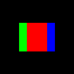
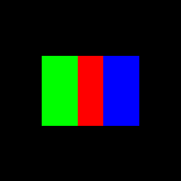
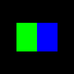
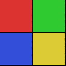
A quad is two triangles sharing a diagonal. Colors on the shared vertices must match for the gradient to be seamless across the diagonal edge, the interpolator only sees per-vertex data, not the neighbouring triangle:
2
0 0 255 80 0   255 0 255 80 0   255 255 255 160 0
0 0 255 80 0   255 255 255 160 0   0 255 255 200 0
png2scene.py generates .scene files from images: resize to N×N, sample one color per cell, emit two triangles per cell at identical vertex colors. The output is a valid .scene file feeding into the same testbench path as any hand-authored scene. At N=256 on a 256×256 framebuffer that is 131,072 lines.
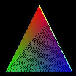
The first render:

One triangle, three vertex colors. The gradient is the interpolator computing w0*c0 + w1*c1 + w2*c2 / area2 at every covered pixel. At 256x256:
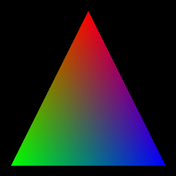
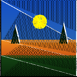
From there: quads as two triangles sharing a diagonal, then a sunset scene with a sky gradient that works because upper and lower vertices of the same triangle carry different colors and the interpolator blends between them per pixel.
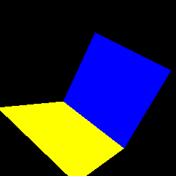
| Quads at 64x64 | Quads at 256x256 | Sunset at 64x64 | Sunset at 256x256 |
|---|---|---|---|
 |  |  |  |
At this point the hardware was handling multiple triangles per frame correctly and interpolation output looked clean. The next question was whether it would hold under a much larger triangle count with no gaps between draws.
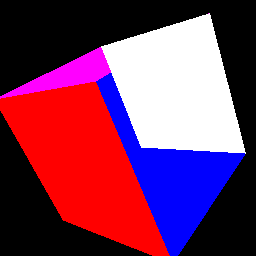
| triangle | quad | sunset | rubiks | rubiks3d |
|---|---|---|---|---|
 |  |  |  |  |
| lissajous | mountains | staircase | rainbow |
|---|---|---|---|
 |  |  |  |
| pyramid | colorwheel | lighthouse | spaceship |
|---|---|---|---|
 |  |  |  |
Photograph Reconstruction
png2scene.py converts any image to a scene file. It resizes the input to an NxN grid, samples one color per cell, and emits two triangles per cell, a quad split diagonally, with all three vertices at the same sampled color. At 256-cell resolution on a 256x256 framebuffer that is 131,072 triangles.
The source image:

Progressive render as the testbench dispatches triangles:
| MJ frame 0 | MJ 6k triangles | MJ 16k triangles | MJ 32k triangles |
|---|---|---|---|
 |  |  |  |
| MJ 65k triangles | MJ 98k triangles | MJ final 256x256 | MJ progressive GIF |
|---|---|---|---|
 |  |  |  |
The reconstruction exercise confirmed that the hardware handles back-to-back triangle dispatch without stalling and that the framebuffer bounds check silently drops out-of-range writes without corrupting in-range pixels. With that settled, the next step was animation.
Animation Infrastructure
Static scene files work for still images. For a rotating object, geometry has to change per frame. The first attempt used a JSON-based streaming format: define the scene declaratively, have Python interpret it per frame, and pipe triangle data to the testbench without writing per-frame scene files.
{
  "frames": 120,
  "objects": [
    {
      "type": "cube_wireframe",
      "center": [128, 128],
      "size": 60,
      "color": [255, 255, 255],
      "motion": { "type": "rotate", "speed": 0.05 }
    }
  ]
}
The first render from that approach:
Something rendered. Three things failed immediately afterward.
The testbench expected a bare integer frame count before the triangle data stream. The JSON "frames": 120 field existed but was not being serialized into the stream header, so the testbench read nothing it recognized and exited. Fixed. Then only frame 0 ever rendered: the frame-advance loop in the testbench was never implemented. The "frames" value was being parsed but not used to drive a loop. Fixed. Then the framebuffer was never cleared between frames, so each new frame accumulated on top of the previous one:

The clear was one line. But by this point the JSON format had no path to 3D vertex coordinates, no keyframing, and no per-object transforms beyond a speed scalar. Extending it to cover what was actually needed would have meant redesigning it from scratch, so it was discarded in favour of a purpose-built format.
The replacement is .anim. OBJECT blocks define named 3D triangle meshes where each vertex carries an explicit Z coordinate. FRAME blocks define keyframe transforms at specific frame numbers, with linear interpolation between them. anim2frames.py reads the file, interpolates transforms per frame, projects into screen space, culls backfaces, sorts surviving triangles by average Z back to front, and writes one .scene file per frame. The hardware only ever sees flat 2D triangles.
OBJECT cube
TRI -42 -42 50 255 0 0  42 -42 50 255 0 0  42 42 50 255 0 0
...
END

FRAME 0
cube ROTATE_X 30
cube ROTATE_Y 45
cube TRANSLATE 128 128 0
cube SCALE 1.0
END

FRAME 120
cube ROTATE_X 30
cube ROTATE_Y 405
cube TRANSLATE 128 128 0
cube SCALE 1.0
END
.anim File Format
An .anim file is structured as a sequence of OBJECT blocks followed by a sequence of FRAME blocks. Any line starting with # is a comment. Blank lines are ignored.
OBJECT block. Opens with OBJECT <name> and closes with END. Between those, every line is a TRI definition, one triangle of the mesh, 15 integers, same column order as .scene but with 3D Z coordinates for each vertex:
TRI x0 y0 z0 R0 G0 B0 x1 y1 z1 R1 G1 B1 x2 y2 z2 R2 G2 B2
Coordinates are integer model-space units, typically in the range [−100, 100]. Colors are 8-bit per channel. An object can contain any number of TRI lines. Multiple OBJECT blocks in one file define independently transformable meshes.
OBJECT layer_top
TRI -42 42 42 255 80 0  42 42 42 255 80 0  42 -42 42 255 80 0
TRI -42 42 42 255 80 0  42 -42 42 255 80 0  -42 -42 42 255 80 0
# ... more triangles
END
FRAME block. Opens with FRAME <n> where n is a frame index (0-based integer), closes with END. Between those, each line is a transform command applied to a named object:
<object_name> <TRANSFORM> <value(s)>
Supported transforms:
ROTATE_X  <degrees>          — X-axis rotation in degrees (float)
ROTATE_Y  <degrees>
ROTATE_Z  <degrees>
SCALE     <factor>           — uniform scale (float; 1.0 = no change)
TRANSLATE <tx> <ty> <tz>    — translation (tz is ignored; translate is post-projection)
Not every object needs to appear in every frame. If an object is missing from a frame block, anim2frames.py uses the nearest defined keyframe values for that object. All transforms for a given frame are applied independently per object, so layer_top, layer_mid, and layer_bot can each have different ROTATE_Y values at the same frame index.
Keyframe interpolation. anim2frames.py linearly interpolates all numeric values between the two surrounding FRAME blocks. Angles interpolate as bare floats (no shortest-path wrapping), so a ROTATE_Y going from 45 to 405 over 120 frames produces exactly one full rotation without any discontinuity.
t = (frame - f0) / (f1 - f0)   # 0.0..1.0
val = v0 + t * (v1 - v0)        # linear blend
For the Rubik’s cube animation this means each layer’s ROTATE_Y track is authored independently per layer, and the three tracks interpolate independently, the solve sequence is authored by choosing which keyframes to put which layer’s Y offset in.
Output pipeline. For each frame, anim2frames.py:
- Interpolates all transform values at the current frame index
- Builds the rotation matrices from
ROTATE_X/Y/Zvalues and applies them, then appliesSCALE, in that order - Projects surviving vertices to screen space with
project()using theTRANSLATEvalues as screen-center offsets - Culls back-facing triangles via the cross-product sign check
- Sorts all surviving projected triangles by average Z (back to front, painter’s algorithm)
- Writes a
.scenefile with the count on line 1 and one projected triangle per line
The sort at step 5 is the painter’s algorithm substitute for hardware Z-buffering. It works correctly for convex objects with no intersecting triangles. It fails for objects that interpenetrate or for concave geometry where triangles genuinely cross in depth, which is the exact problem the hardware Z-buffer in the 3D port is intended to solve.
The transform stack applies scale, rotate Y, rotate X, rotate Z, in that order. Translation is a screen-space offset applied after the perspective divide.
def project(v, tx, ty, fov=300, camera_z=200):
    z = v.z + camera_z
    if abs(z) < 0.001: z = 0.001
    px = int(v.x * fov / z) + tx
    py = int(v.y * fov / z) + ty
    return px, py
The RTL port in prim_assembly.sv replicates this formula with integer arithmetic after stripping fractional bits. The near-zero guard if abs(z) < 0.001 maps to if (z_int == 0) z_int = 1 in the proj_coord function. Python’s int() truncation and integer fixed-point division truncate toward zero identically for positive values, so the projected pixel coordinates match the Python output when no rounding difference accumulates across the Q10.6 representation.
Backface culling uses the Z component of the cross product of two edges in transformed 3D space, before projection.
def is_backface(v0, v1, v2):
    ax = v1.x - v0.x; ay = v1.y - v0.y
    bx = v2.x - v0.x; by = v2.y - v0.y
    nz = ax * by - ay * bx
    return nz > 0
The hardware version (prim_assembly.sv) computes the same cross product in view-space Q10.6 on the cycle the third vertex arrives, right-shifting both factors by 6 to work in integers and avoid 32-bit overflow. The cull comparison is cull_nz <= 0 rather than > 0 because prim_assembly emits the triangle when the condition is true; the polarity is logically identical. Shifting by 6 before the multiply loses fractional precision but preserves sign, and the cull decision is a sign check so the precision loss does not affect correctness:
cull_nz <= ($signed(buf_x[1]-buf_x[0]) >>> 6) * ($signed(in_y-buf_y[0]) >>> 6)
          -($signed(buf_y[1]-buf_y[0]) >>> 6) * ($signed(in_x-buf_x[0]) >>> 6);
if (cull_nz <= 0) begin
    tri_valid <= 1;   // front-facing — fire triangle
    v0x <= proj_coord(buf_x[0], buf_z[0], fov_q6, cam_z_q6, trans_x);
    // ... v1, v2
end
Getting a Cube to Look Like a Cube
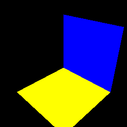
The first .anim file had a cube doing pure Y rotation with Z dropped after transforms, orthographic projection.
| Frame 0 | Frame 5 | Frame 10 | Frame 15 | Frame 20 | Frame 80 |
|---|---|---|---|---|---|
 |  |  |  |  |  |
Frame 0 is a flat red square. Side faces appear as zero-foreshortening rectangles. Only two faces ever show because there is no X tilt exposing the top or bottom. Each subsequent change produced a different failure.
Adding perspective projection breaks the screen center.
Added perspective projection and ROTATE_X 25. The cube immediately flew off screen.
| Frame 0 | Frame 30 | Frame 90 |
|---|---|---|
 |  |  |
TRANSLATE 128 128 0 was being applied in 3D space before the perspective divide. The (128, 128) screen-center offset was being divided by Z along with the vertex coordinates, so as vertex Z values changed during rotation the projected center drifted. Moving translation to after the divide fixed it.
Edge-on degeneracy at the starting angle.
With translation fixed, the cube still showed only two faces at certain angles. The starting angle was ROTATE_Y 30. At that angle the cube passes through edge-on positions during rotation where one face collapses to a sliver.

| Frame 0 | Frame 90 |
|---|---|
 |  |
Changing to ROTATE_Y 45, corner-on, ensures three faces are always visible throughout the full rotation.
Screen-space backface culling produces alternating artifacts.
Backface cull using the signed area of the projected 2D triangle. Screen Y increases downward, which flips the sign convention. The cull alternated between correct and inverted depending on rotation angle.

| Frame 0 | Frame 30 |
|---|---|
 |  |
Frame 30 shows all six faces simultaneously, back faces drawing on top of front faces. Flipping the comparison sign only swapped which angles were wrong. Moving the cull into 3D view space and checking the Z component of the face normal directly removed the dependence on screen-space coordinate conventions.
Wrong rotation order.
Rotation was being applied X then Y. The correct order for spinning around a vertical axis while tilted is Y then X. Applying X first rotates the tilt axis along with the cube, so the axis of spin precesses.
| Frame 0 | Frame 90 |
|---|---|
 |  |
Fixed to Y then X then Z.
Three faces had inverted winding from the start.
After all of the above, a persistent problem remained at specific angles. Checking every face by computing dot(normal, centroid_from_origin):
front:  dot > 0  outward  OK
back:   dot > 0           OK
left:   dot < 0  INWARD   WRONG
right:  dot > 0           OK
top:    dot < 0  INWARD   WRONG
bottom: dot < 0  INWARD   WRONG
Left, top, and bottom had vertices wound in the wrong order in the original mesh. Their normals pointed inward, so when those faces were facing the camera they were culled, and when facing away they rendered. This was invisible in the orthographic version because there was no culling at all. Reversing vertex order on those three faces and re-running the dot product check on all six resolved it.
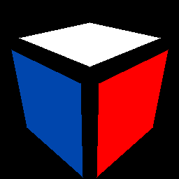
After all of these iterations:
| Frame 0 | Frame 45 | Frame 90 |
|---|---|---|
 |  |  |
Three faces visible and stable through the full rotation. First time it looked like an actual 3D object.
Rubik’s Colors and Sticker Separation
| Face | Color | RGB |
|---|---|---|
| Top (y = -50) | White | 255, 255, 255 |
| Bottom (y = +50) | Yellow | 255, 213, 0 |
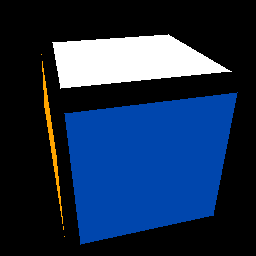
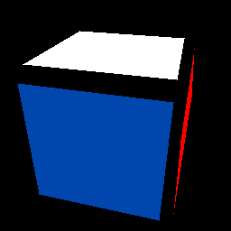
| Front (+z) | Red | 255, 0, 0 |
| Back (-z) | Orange | 255, 165, 0 |
| Left (-x) | Green | 0, 155, 72 |
| Right (+x) | Blue | 0, 70, 173 |

Correct colors but solid flat faces with no sticker separation. Looks like a painted box. The rasterizer only draws filled triangles, so black border geometry would mean coplanar triangles at nearly identical Z values fighting through the painter’s sort. The alternative: shrink each face’s four corners toward the face center by 15% in 3D space before projection. The framebuffer background is black. Where nothing is drawn, black shows through. The gaps become the grout lines with no extra geometry.
def shrink(verts, factor=0.85):
    cx = sum(v[0] for v in verts) / len(verts)
    cy = sum(v[1] for v in verts) / len(verts)
    cz = sum(v[2] for v in verts) / len(verts)
    return [
        (round(cx + (v[0]-cx)*factor),
         round(cy + (v[1]-cy)*factor),
         round(cz + (v[2]-cz)*factor))
        for v in verts
    ]
Shrinking in 3D before projection makes gap width perspective-correct automatically. Rewriting the face generation code to incorporate the shrink changed the vertex ordering and broke winding on three faces again. The dot product check re-run on all six faces caught and fixed them.

| Frame 0 | Frame 60 |
|---|---|
 |  |
Scaling to 3x3

| Frame 0 | Frame 10 | Frame 20 | Frame 30 | Frame 60 | Frame 90 |
|---|---|---|---|---|---|
 |  |  |  |  |  |
Moving to 3x3: 9 stickers per face, 6 faces, 54 stickers. Cube spans ±63 units. Each face has sticker coordinate slots at -58 to -26, -16 to +16, +26 to +58. The 10-unit gaps produce the black grout lines when the background shows through.
The first attempt used layered geometry: a full-cell black quad per sticker with a smaller colored quad on top. Three problems appeared simultaneously. The cube overflowed the frame because a 3x3 at 126 units is 50% wider than the 1x1 at 84 units. Several faces had wrong winding. And even on correct faces, individual triangles were visible rather than solid stickers.
| mid_140 | chk_210 | chk_090 | chk_000 |
|---|---|---|---|
 |  |  |  |
The triangle artifact came from the painter’s sort: 18 triangles per face at nearly identical Z values meant the sort order between the black and colored layers was not stable across stickers. Some stickers showed only the black triangle, others only the colored one.
The fix was to remove all black geometry entirely. The background is already black. Draw only the colored stickers with coordinate gaps between them and let the background serve as the borders. Removing the black layer also eliminated every Z-fighting scenario by removing the second layer. Scale corrected by SCALE 0.55. Winding re-verified with the dot product check at 8 different rotation angles.

| Frame 0 | Frame 15 | Frame 30 | Frame 45 |
|---|---|---|---|
 |  |  |  |
| Frame 60 | Frame 75 | Frame 90 | Frame 105 | Frame 119 |
|---|---|---|---|---|
 |  |  |  |  |
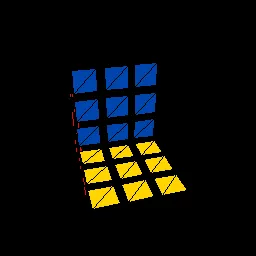
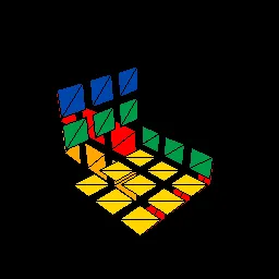
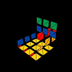
Layer-by-Layer Solve Animation
With a working 3x3, the cube was split into three independent object blocks, one per horizontal layer, each with its own ROTATE_Y transform. The scrambled start gives each layer a different Y rotation offset on top of the shared base spin. Keyframes interpolate those offsets back to zero in sequence: bottom layer solves frames 15-35, middle frames 35-55, top frames 55-75.
FRAME 0
layer_top ROTATE_Y 135.00
layer_mid ROTATE_Y -45.00
layer_bot ROTATE_Y 225.00

FRAME 75
layer_top ROTATE_Y 270.00
layer_mid ROTATE_Y 270.00
layer_bot ROTATE_Y 270.00

FRAME 120
layer_top ROTATE_Y 405.00
layer_mid ROTATE_Y 405.00
layer_bot ROTATE_Y 405.00
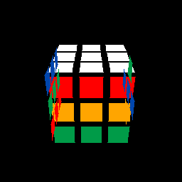
Per-Sticker Color State and the Full Solve
Beyond the layer animation, a complete Rubik’s cube state simulator was built to render an actual scramble-and-solve sequence with per-sticker colors updating after each move. All 18 move types are implemented as explicit sticker permutations. The back and left faces have coordinate systems mirrored relative to a front viewer, so their index mapping under moves like U requires reversal:
if base == 'U':
    c['F'][0],c['F'][1],c['F'][2] = f['L'][0],f['L'][1],f['L'][2]
    c['R'][0],c['R'][1],c['R'][2] = f['F'][0],f['F'][1],f['F'][2]
    c['B'][2],c['B'][1],c['B'][0] = f['R'][0],f['R'][1],f['R'][2]  # reversed
    c['L'][0],c['L'][1],c['L'][2] = f['B'][2],f['B'][1],f['B'][0]  # reversed
Getting one reversal wrong makes a scramble look like a solve. The permutations were verified with the sexy move R U R' U' repeated six times returning to solved, each face rotated four times, and a full scramble-plus-solution round trip.
Scramble: F R U' R' U' R U R' F' R U R' U' R' F R F'
Solution: F R' F' R U R U' R' F R U R' U' R' F' R U' R'
The animation spans 20 states: scrambled plus one per solve move. Each state is a separate object block with different vertex colors. In each frame, one object sits at the screen center and all others are translated to Y = -2000, off-screen, where the framebuffer bounds check discards their pixels. The state snap takes one frame, imperceptible at playback speed.
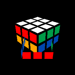
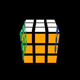
SIMD: Current Issue
The FIFO pop arbitration is a free-running round-robin counter:
always_ff @(posedge clk or negedge rst_n) begin
    if (!rst_n) rr_grant <= 2'd0;
    else        rr_grant <= rr_grant + 2'd1;
end
Lane $n$ pops only when rr_grant == n && !fifo_empty[n]. The counter increments every cycle regardless of whether the selected FIFO is empty. When a lane’s FIFO is empty on its grant cycle, the slot is wasted and the grant advances to the next lane. Under uneven fill conditions, which happen constantly, since triangle coverage is not uniform across lanes, lanes with more fragments fall behind while their grant slots are skipped. Over a triangle with heavy coverage on lanes 0 and 1 and sparse coverage on 2 and 3, the FIFOs for 0 and 1 fill faster than the round-robin drains them, eventually backpressuring the rasterizer. When the rasterizer stalls mid-row and then resumes, the per-lane edge accumulators are correct but the pixel coordinates already sitting in partially-filled FIFOs no longer match the winding of the arbitration counter, producing out-of-order writes to the framebuffer.
The root of the problem is that the counter has no visibility into FIFO occupancy; it allocates grant slots uniformly regardless of which lanes actually have work. A minimum fix is a request-masked round-robin that only advances when the granted lane actually fired, which would eliminate the wasted slots:
// masked round-robin: hold grant until selected lane has data
wire [3:0] req = ~fifo_empty;
always_ff @(posedge clk or negedge rst_n) begin
    if (!rst_n) rr_grant <= 2'd0;
    else if (req[rr_grant])      // lane has data → consume and rotate
        rr_grant <= rr_grant + 2'd1;
    // else: stall on this lane until it fills — no wasted cycles
end
This removes the empty-slot waste but introduces head-of-line blocking: a lane that fills slowly holds the grant for all other lanes until it delivers. The warp scheduler is intended to replace both behaviors by selecting only lanes belonging to ready active warps, skipping empty lanes dynamically, and retiring a warp only after all valid fragments from that raster step have completed. That preserves issue locality and removes the ordering loss introduced by blind cyclic grants.
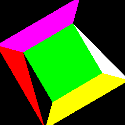
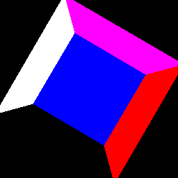
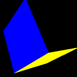
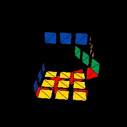
The images below are from this SIMD build, using the same scenes as earlier in this post as regression targets:
| Hello Triangle (SIMD) | Quads (SIMD) | Sunset (SIMD) |
|---|---|---|
 |  |  |
The triangle gradient tears where lane drain order diverges from rasterization order. The quad boundaries show diagonal smearing from mis-sequenced FIFO pops. The sunset loses color coherence across the sky gradient. Edge evaluation, coverage, and interpolation math are all correct when driven single-lane, the round-robin arbitration is the isolated failure point.
SIMD: Warp Scheduler Approach and the Issues it Exposed
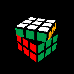
The next attempt replaced the per-lane FIFO model with a dedicated warp_scheduler module sitting between the rasterizer and the interpolator. The rasterizer remained single-pixel-per-cycle and passed fragments one at a time to warp_scheduler, which buffered them in an internal array until it accumulated WARP_SIZE fragments or received rast_done, then dispatched the completed warp. simd_interp and simd_pixel_shader processed all warp lanes simultaneously, and writeback_coalescer serialised the results back to the framebuffer one pixel at a time.
There were two structural problems with this approach.
The first was backpressure. frag_ready from the warp scheduler was !dispatching && warp_ready. When the scheduler entered DISPATCH state it stopped accepting fragments from the rasterizer, which had to stall. On the return path from DISPATCH back to ACCUMULATE, there was a one-cycle gap where frag_ready went low and then high again. The rasterizer would resume on the next cycle but the handshake meant it could miss a fragment on the cycle the scheduler re-entered ACCUMULATE. On partial warps at triangle end, saw_rast_done gated the dispatch condition, but rast_done is a single-cycle pulse, if it landed during the one cycle when the scheduler was transitioning state, it was not registered correctly and the final partial warp could fail to dispatch.
The second was the serialised writeback. writeback_coalescer in this version had a two-state FSM: IDLE to buffer the incoming warp, then WRITE to step through it one pixel per cycle. For a warp of size 8, this takes 8 cycles to drain. During those 8 cycles warp_ready was low, stalling the shader, which stalled the interpolator, which stalled the rasterizer via FIFO backpressure. The effective throughput ceiling was 1 pixel per 8 cycles from the coalescer alone, completely negating the parallel execution upstream.
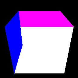
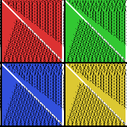
The output images from this version have scattered lost pixels, visible as incorrect or missing pixels near triangle edges, the result of fragments dropped in the handshake gap or written with stale warp state:
| Hello Triangle | Quads | Sunset |
|---|---|---|
 |  |  |
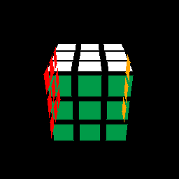
Zoomed Images
| Hello Triangle | Quads | Sunset |
|---|---|---|
 |  |  |
SIMD: What Was Fixed
The third implementation restructured all three problem areas.
Rasterizer parallelism. Rather than keeping the rasterizer single-pixel and adding a scheduler to batch fragments, the rasterizer itself was extended with an OUT_W parameter. With OUT_W=8, each SCAN cycle tests 8 horizontally adjacent pixels simultaneously and outputs them as a single masked warp. Lane $n$ evaluates $E_{ij}(\text{minx} + cx + n, cy)$ using the row-start accumulator plus $n \cdot A_{ij}$, computed combinationally with a generate loop:
wire signed [31:0] off01 = rA01 * $signed(32'd0 + gi);
assign lane_e01[gi]     = e01 + off01;
assign lane_covered[gi] = (lane_e01[gi] >= 0) &&
                          (lane_e12[gi] >= 0) &&
                          (lane_e20[gi] >= 0);
assign lane_in_row [gi] = (lane_px[gi] <= rMaxx);
out_valid is a single bit (at least one lane covered), out_mask is an OUT_W-bit vector with one bit per covered-and-in-row lane, and cx advances by step, min(OUT_W, pixels_remaining_in_row), not by 1. The rasterizer stalls only when !out_ready and any_covered. Uncovered warp steps advance freely with no stall.
Warp FIFO. The warp scheduler FSM was replaced with a frag_fifo instance sized to hold full warp payloads. At WARP_SIZE=8 the payload is 1664 bits: mask (8) + px (128) + py (128) + w0/w1/w2 (256 each) + area2 (256) + vertex colors (192 each). The rasterizer pushes a warp on every out_valid && !warp_fifo_full cycle. Backpressure is out_ready = !warp_fifo_full. The interp pops whenever it can accept. There is no scheduler FSM, no dispatching state, no missed-pulse risk:
assign warp_fifo_pop = !warp_fifo_empty && interp_ready;
always_ff @(posedge clk or negedge rst_n)
    if (!rst_n) fi_valid <= 1'b0;
    else        fi_valid <= warp_fifo_pop;
Parallel writeback. writeback_coalescer was rewritten as a purely combinational module. It forwards the entire warp to framebuffer_mp in a single registered cycle. warp_ready is permanently tied high. framebuffer_mp has WARP_SIZE parallel write ports, each independently bounds-checked and masked, all firing in the same clock edge:
// All WARP_SIZE lanes write in one always_ff block
if (warp_wr_en) begin
    for (int i = 0; i < WARP_SIZE; i++) begin
        if (warp_mask[i]) begin
            if (lane_px[i] >= 0 && lane_px[i] < $signed(WIDTH) && ...)
                mem[lane_py[i] * WIDTH + lane_px[i]] <= {warp_r[i*8+:8], ...};
        end
    end
end
The mask bit per lane propagates from the rasterizer’s coverage test through the warp FIFO, through simd_interp and simd_pixel_shader unchanged, and into framebuffer_mp. Lanes that fall outside the triangle boundary or past the row end have their mask bit cleared at the rasterizer and never write. The coalescer no longer serialises; it introduces one pipeline register and then the framebuffer accepts the full warp in one cycle.
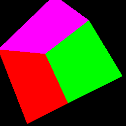
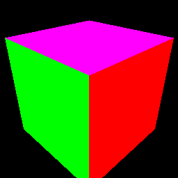
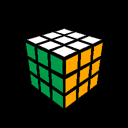
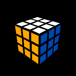
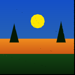
The same three scenes, now clean:
| Hello Triangle | Quads | Sunset |
|---|---|---|
 | 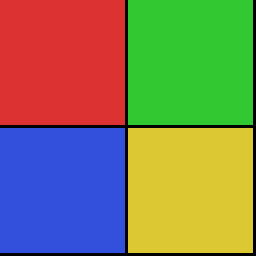 |  |
The three scenes were run under both the baseline scalar build and the SIMD build to get a direct cycle comparison. Numbers from the simulation logs:
Hello triangle (1 triangle, 25,313 pixels): baseline 50,670 cycles at 0.4996 px/cyc; SIMD 6,580 cycles at 3.847 px/cyc. Wall-clock reduction of 87%. The rasterizer ran 99.16% busy in SIMD mode, rast backpressure zero, the warp FIFO absorbed the burst without stalling the scan walk. Warp dispatch active 51.08% of wall-clock, average 7.53 active lanes per warp. The sub-8 average comes from partial warps at the row ends and the triangle’s two near-horizontal edges where the last warp in each row may have fewer than 8 covered pixels.
Quads (8 triangles, 63,000 pixels): baseline 125,220 cycles at 0.503 px/cyc; SIMD 16,300 cycles at 3.865 px/cyc. Reduction of 87%. The quads are axis-aligned rectangles split diagonally, each triangle is roughly half the screen area, so coverage per row is dense and warp fill is high. Average 7.41 lanes/warp across all 8 triangles.
Sunset (20 triangles, 72,752 pixels): baseline 146,736 cycles at 0.4958 px/cyc; SIMD 19,426 cycles at 3.745 px/cyc. Reduction of 87%. The sunset has several small triangles in the horizon detail (triangles 6–17 in the log, each around 157–160 pixels) where per-triangle warp count is low and the partial-warp overhead dominates. Those triangles land between 1.57 and 1.86 px/cyc individually. The large sky gradient triangles (triangles 0–5) hit 3.89–3.93 px/cyc, close to the 4× theoretical maximum for warp size 8 given that fill efficiency is 50%.
Rast backpressure is zero in all three SIMD runs. The warp FIFO depth of 16 is sufficient to absorb the rasterizer’s burst without ever asserting !out_ready. This means the rasterizer never stalls waiting for downstream, its busy percentage reflects the actual triangle geometry, not pipeline congestion.
What This Was Actually For
The goal was a synthesisable fixed-function rasteriser in hardware. The 3x3 cube solve animation was picked as a target exercise because it exercises the full datapath simultaneously and at scale: multiple triangles, per-frame state changes, and enough pixels that partial-warp behaviour shows up in the numbers. Bugs invisible in a single static triangle surface immediately in a multi-object animated scene with per-frame state changes.
The SIMD architecture required a working verified baseline to regression-test against. Every triangle in every scene was checked against a golden pixel count before parallelism was introduced, so any divergence from the SIMD changes could be isolated immediately rather than blamed on the underlying edge arithmetic. That is what this established.