
RV32I CPU CORE

This project implements a basic RV32I RISC-V processor core using TL-Verilog. The processor is capable of executing the base integer instruction set, with an example program that calculates the sum of integers from 1 to 9. The code is written for Makerchip and is fully synthesizable and testable in simulation.
Overview
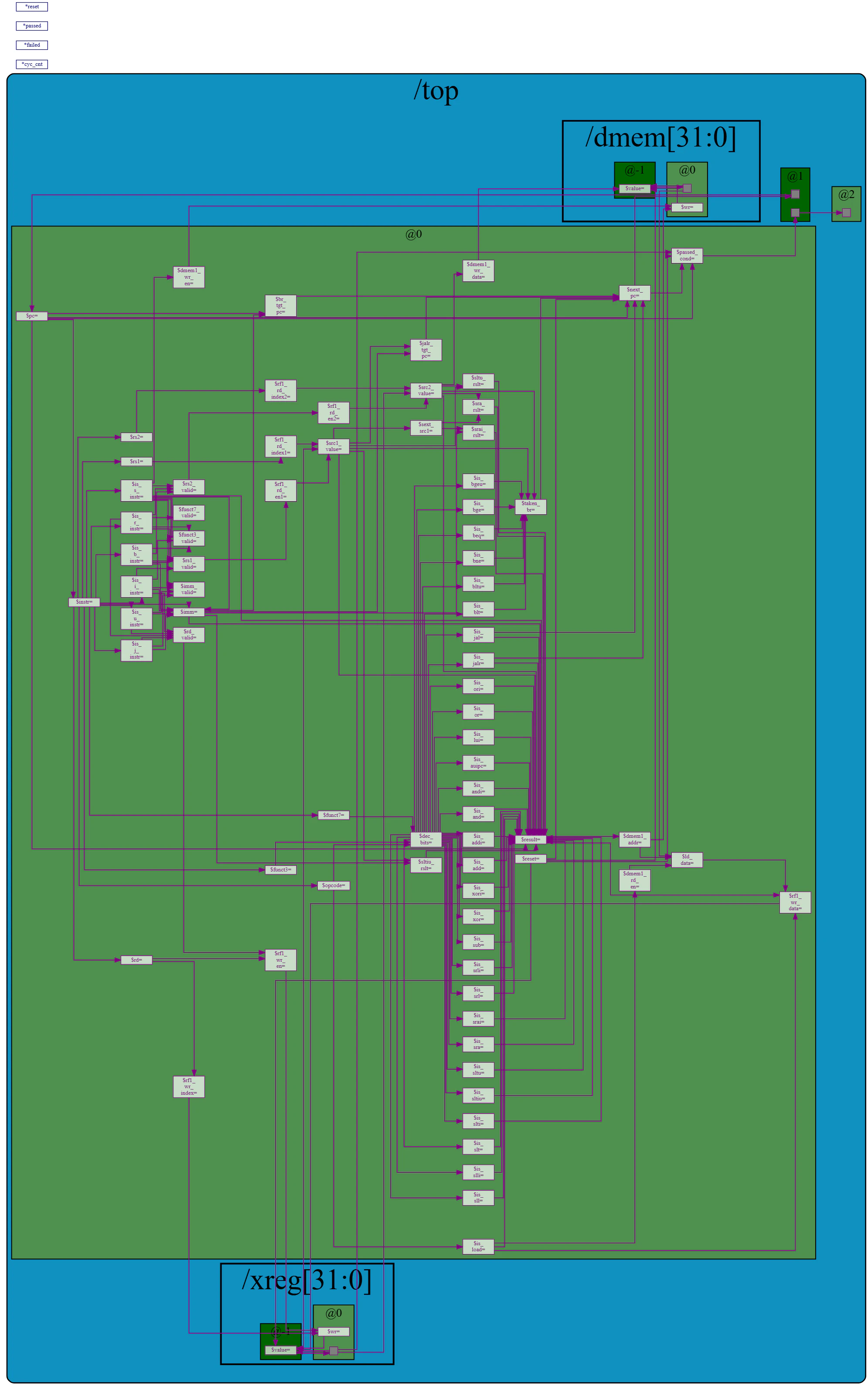
The design uses a single-stage architecture with instruction fetch, decode, execution, and memory access logic implemented in TL-Verilog. The core uses a program counter $pc, instruction memory $instr, and a 32-register file. It supports all immediate types (I, S, B, U, J), arithmetic and logic operations, and basic branching and jumping.
Program
The initial program is stored in the section m4_asm. It loads a simple loop that:
- Sets register
x12to 10 as the loop end - Increments register
x13from 1 to 9 - Accumulates the sum in register
x14 - Sets
x30if the sum is correct - Sets
x31if the test fails
The purpose of this program is to verify that the core can perform register arithmetic and branching correctly.
Instruction Memory
The instruction memory is read-only and provides 32-bit instructions from the address held in $pc. It is instantiated using the Makerchip macro READONLY_MEM($pc, $$instr). The instructions are stored in little-endian order and aligned to 4-byte boundaries.
Instruction Decode
Instruction decode logic uses:
opcodefield at bits [6:2] to classify instruction typefunct3andfunct7fields to identify specific ALU operationsrd,rs1, andrs2fields to access register addresses
Decoded flags such as $is_add, $is_sub, $is_beq, $is_jal, and $is_jalr are derived from instruction fields to simplify control logic.
ALU Logic
ALU operations are determined based on the decoded instruction. The source operand values are read from $src1_value and $src2_value. These are selected from the register file and immediate values depending on the instruction type.
The ALU supports:
- Arithmetic:
$is_add,$is_sub,$is_addi - Logical:
$is_and,$is_or,$is_xor,$is_andi,$is_ori,$is_xori - Shifting:
$is_sll,$is_srl,$is_sra, including immediate shift types - Comparison:
$is_slt,$is_sltu,$is_slti,$is_sltiu
Results from the ALU are stored in $alu_result.
Immediate Value Extraction
The design supports all RISC-V immediate formats. Immediate values are extracted into $imm based on instruction type flags:
- For I-type, bits [30:20] are sign-extended
- For S-type, bits [11:7] and [30:25] are concatenated and sign-extended
- For B-type, bits [11], [10:5], [4:1], [31] are reordered and sign-extended
- For U-type, upper 20 bits are used with lower bits set to zero
- For J-type, bits are reordered similarly to form the jump target
These are used as the second operand in ALU calculations or as offsets in control flow instructions.
Register File
The core uses a 32-register file (x0 to x31) with dual-read and single-write capabilities. Register x0 is hard-wired to zero using a write-enable mask:
$wr_enis true only when$rd_validis set and$rdis not zero$rd,$rs1, and$rs2are extracted from the instruction- Values are read from
$src1_valueand$src2_value - Results are written back to the register file using
$wr_data
The register file is instantiated using m4+rf(32, 32, ...).
Program Counter and Control Flow
The program counter $pc determines the instruction to fetch each cycle. It is updated based on instruction type:
- On reset,
$pcis set to zero - For jumps and branches,
$br_tgt_pcor$jalr_tgt_pcis selected - If no branch is taken,
$pcincrements by 4
Branch target addresses are calculated using:
$br_tgt_pc=$pc+$imm$jalr_tgt_pc=$src1_value+$imm
The next PC is selected using a priority multiplexer with $taken_br, $is_jal, and $is_jalr flags.
Branch and Jump Control
Branch decisions are made using a combinational block that evaluates conditions:
$is_beq: branch if equal$is_bne: branch if not equal$is_blt: branch if less than (signed)$is_bge: branch if greater or equal (signed)$is_bltu: branch if less than (unsigned)$is_bgeu: branch if greater or equal (unsigned)
The condition results are used to set $taken_br, which influences the $next_pc logic.
Data Memory (Load/Store)
Data memory is declared using m4+dmem(32, 32, ...), which is ready to handle load and store instructions. Though not used in the example program, the memory supports:
$ld_en: load enable signal$st_en: store enable signal$dmem_addr: effective address$dmem_wr_data: store data$dmem_rd_data: read result
Instruction decoding for LW, SW, and other memory operations is included for extensibility.
Test and Debug Support
Simulation is capped by M4_MAX_CYC, defined as 50 cycles. If the program does not finish by then, the core sets *failed.
Two registers indicate test results:
x30is set to 1 when the final sum is correct (i.e., 45)x31is set to 1 if the sum is incorrect
The test program loops using beq and exits by jumping to its own address after completion. This allows easy validation of loop control and ALU functionality.
Makerchip Integration
The code includes m4+cpu_viz() for simulation and visualization in Makerchip. This enables waveform inspection and debugging without extra setup.
To run the simulation:
- Paste the code into Makerchip
- Click run to simulate
- View registers and waveform to ensure correct behavior
Check if register x14 equals 45 to confirm successful execution.
Here’s a concise explanation of the results flow in Makerchip’s TL-Verilog toolchain:
Results Flow in Makerchip
top.tlv— Your original TL-Verilog source code file. This file is processed by a Perl script to generate an intermediate macro-expanded file:top.m4.pre— A preprocessed TL-Verilog file with macros expanded, ready for the M4 macro processor. The M4 macro processor then transforms this into:top.m4— The fully macro-expanded TL-Verilog file, prepared for further processing by SandPiper. SandPiper takes this file and generates synthesizable SystemVerilog code:top.svandtop_gen.sv— Generated SystemVerilog files from TL-Verilog, suitable for simulation and synthesis. These files can then be passed to Verilator for cycle-accurate simulation.vlt_dump.vcd— The output waveform dump file generated by Verilator during simulation. This VCD (Value Change Dump) file can be opened in third-party waveform viewers such as drom.io Surfer to visualize signal activity and debug the design.