Brevitas + FINN
CIFAR-10 CNN Inference — Brevitas + FINN FPGA Deployment
End-to-end quantization-aware training and hardware deployment of a ResNet-style
CIFAR-10 classifier on the Digilent Zybo Z7-10 (Zynq-7010,
xc7z010clg400-1) using PyTorch, Xilinx Brevitas, QONNX export, and the FINN
compiler. The pipeline produces a functional .bit bitstream for direct FPGA
deployment.
This is distinct from the manual HLS and hls4ml approaches documented elsewhere. FINN generates a streaming dataflow hardware architecture — every layer becomes a dedicated streaming IP block connected by FIFOs — rather than a single monolithic kernel.
Toolchain
| Tool | Role |
|---|---|
| PyTorch | Model definition and training |
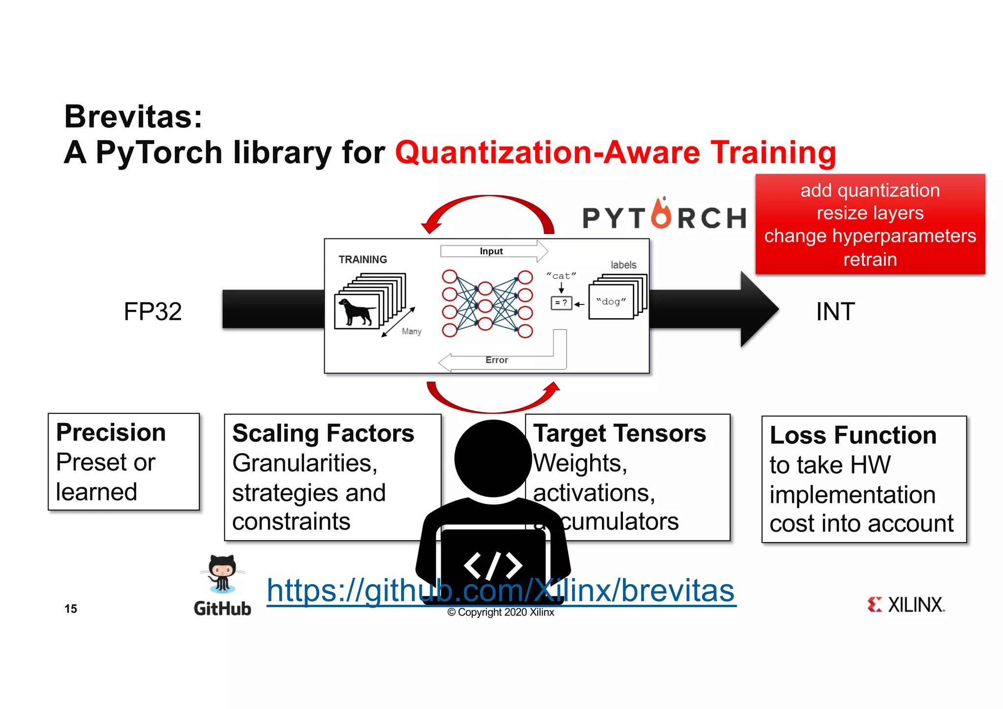
| Brevitas | Quantization-aware training (QAT) |
| QONNX / QONNXManager | Export quantized model to ONNX-based interchange format |
| FINN compiler | Dataflow compilation, HLS/RTL IP generation, Vivado integration |
| Vivado 2022.2 | Synthesis, place and route, bitstream generation |
Model Architecture
A custom ResNet-style network designed specifically for the resource constraints
of the xc7z010 (xc7z010clg400-1): 17,600 LUTs, 35,200 FFs, 80 BRAM_18K
blocks, 80 DSP48s.
Input images are resized to 28×28 (not the standard CIFAR-10 32×32). This reduces the spatial dimensions of all feature maps through the network, directly reducing the memory and logic required for convolution input generators and FIFOs. The architecture uses residual blocks with MaxPool downsampling, no floating-point reductions, and strictly integer arithmetic throughout — all requirements imposed by FINN’s hardware mapping constraints.
Quantization Scheme
FINN requires that every operation in the graph be expressible as integer arithmetic with fixed bitwidths. The quantization scheme was chosen to satisfy this while retaining accuracy:
Input quantization — 8-bit signed
A quantized identity layer is placed at the network input. This scales the incoming pixel values into the 8-bit signed integer range before the first convolution. Without this, the first conv layer receives float inputs and FINN cannot map it to integer hardware.
Weight quantization — 4-bit signed
All convolutional and linear layer weights are quantized to 4-bit signed
integers using Brevitas Int4WeightPerTensorFloat (or equivalent). 4-bit
weights halve the BRAM footprint compared to 8-bit and reduce the bit-width
of the multipliers that FINN generates, which in turn reduces DSP and LUT
usage.
Activation quantization — 4-bit unsigned
Post-ReLU activations are quantized to 4-bit unsigned using Brevitas
QuantReLU. Unsigned is correct here because ReLU outputs are always
non-negative. 4-bit activations match the weight bitwidth, keeping the
multiply-accumulate products at 8 bits before accumulation — well within
ap_fixed ranges and compatible with FINN’s MVAU (Matrix-Vector Activation
Unit) mapping.
The combination of 4-bit weights and 4-bit activations is the most hardware-efficient quantization point that FINN supports for convolutional layers on small Zynq devices.
Training
Dataset and preprocessing
CIFAR-10 with all images resized to 28×28 at load time. Resizing at the dataloader rather than offline means the model trains on the exact input dimensions that the hardware will receive.
Training configuration
- 30 epochs
- GPU acceleration
- DataLoader with pinned memory, multiple CPU workers, and cuDNN benchmarking
enabled (
torch.backends.cudnn.benchmark = True) — standard settings for throughput-optimized GPU training
Export to QONNX
After training:
- Model weights saved to disk.
- Network traced with
torch.jit.traceusing a representative input tensor. - Exported to FINN-compatible QONNX format using
QONNXManager.
The .qonnx file encodes the network graph with quantization annotations
attached to each operator — bitwidths, scale factors, zero points — in a
format that FINN’s transformation passes can parse and lower to hardware.
FINN Environment Configuration
Docker I/O optimization
The FINN compiler runs inside a Docker container. The build directory was
redirected to /tmp inside the container, which is backed by a RAM disk.
This avoids host filesystem latency during the intermediate steps that generate
large numbers of small files: Verilator simulation, C++ HLS compilation, and
FIFO sizing. Host filesystem I/O can become a significant bottleneck during
these steps on machines with slow drives or NFS-mounted home directories.
Dependency version control
Specific compatible versions of Brevitas and QONNX were pinned and installed automatically at container startup. FINN’s transformation passes are sensitive to the QONNX opset version — a version mismatch between the exporter (Brevitas-side) and the consumer (FINN-side) causes silent graph transformation failures where nodes are not recognized and pass through unmodified, producing incorrect hardware.
Custom Zybo Z7-10 Board Integration
The Zybo Z7-10 is not in FINN’s official board support list. FINN ships with
board definitions for Pynq-Z1, Pynq-Z2, ZCU102, and a few others.
xc7z010clg400-1 is not among them. Manual integration was required.
Board definition injection
A board entry was added to FINN’s board registry with:
- Part number:
xc7z010clg400-1 - AXI port width: 32-bit (the Zynq-7010 PS has 32-bit AXI GP and HP ports, unlike the 64-bit ports on larger Zynq UltraScale+ devices)
- Architecture:
zynq_7000
Without this entry, FINN’s Vivado block design generation step does not know the PS configuration and generates incorrect PS–PL wiring.
TCL template modifications
FINN generates a Vivado block design by rendering TCL templates. The templates were modified to:
- Use the correct part string for
xc7z010clg400-1 - Wire AXI-Stream and AXI-Lite ports to the correct Zynq PS slave/master ports
- Bypass FINN’s legacy 10-interface AXI-Lite limit, which was too low for the number of control registers required by the multi-layer ResNet configuration. The limit is a hardcoded constant in the template that was increased.
FINN Compilation Pipeline
The exported QONNX model was passed through FINN’s 17-step dataflow compilation pipeline. Each step is a graph transformation pass operating on the QONNX intermediate representation.
Major stages
1–2. Model transformation and cleanup Canonicalization passes: constant folding, dead node elimination, operator fusion where possible, shape inference. Produces a clean graph with no redundant operations.
3. Streamlining Absorbs scale factors and zero-point shifts from quantization annotations into adjacent layers. After this step, all activations are integer-valued and all weights are integer-valued — there are no floating-point scale multiplications remaining in the graph. This is a prerequisite for hardware mapping.
4. Folding and parallelization Determines the parallelism (PE count, SIMD width) for each layer. This controls the hardware throughput: higher parallelism = more DSPs and BRAMs consumed, lower latency. FINN’s folding step attempts to balance throughput across layers to avoid bottlenecks.
5–6. HLS IP and RTL IP generation
Each layer is lowered to either an HLS C++ implementation (compiled by
Vitis HLS) or a direct RTL implementation. Convolutional layers map to MVAU
(Matrix-Vector Activation Unit) HLS blocks. MaxPool maps to
StreamingMaxPool HLS blocks. Input padding maps to FMPadding RTL blocks.
Data width adapters (StreamingDataWidthConverter) and FIFOs
(StreamingFIFO) are inserted between layers to match bitwidths and buffer
data between pipeline stages.
7. Verilator simulation Functional simulation of the generated RTL to verify correctness before invoking Vivado. Run inside the container against the RAM disk.
8. Dataflow stitching
All individual IP blocks are stitched together into a single streaming
dataflow design. Data moves through the system as AXI-Stream packets: the
DMA engine (IODMA) reads input from DDR, pushes it into the stream, it
flows through convolutions, activations, and pooling layers in sequence, and
the output stream is written back to DDR by a second DMA engine.
9. Vivado block design generation Renders the TCL template to produce a complete Vivado block design containing the Zynq PS, the FINN accelerator partition, AXI-Stream connections, and AXI-Lite control.
10–11. Synthesis and place-and-route
Vivado runs synth_design followed by impl_design. The LD_PRELOAD
memory allocator override (see below) was applied here.
12. Bitstream generation
write_bitstream produces the final .bit file.
Memory stability fix
Vivado 2022.2 has known instability during synthesis and place-and-route on Linux when using the default glibc memory allocator under high memory pressure. Symptoms include random segfaults or hangs during elaboration. The standard workaround is:
LD_PRELOAD=<path_to_libtcmalloc.so>
This replaces glibc malloc with Google’s tcmalloc, which has better
fragmentation behaviour under Vivado’s allocation patterns. This was applied
inside the FINN container before invoking the Vivado steps.
Post-Synthesis Resource Utilization
Top-level summary (xc7z010clg400-1)
| Resource | Used | Available | Utilization |
|---|---|---|---|
| LUT | 11,581 | 17,600 | 66% |
| SRL (shift register LUT) | 879 | — | — |
| FF | 14,557 | 35,200 | 41% |
| BRAM_36K | 17 | 40 | 43% |
| BRAM_18K | 5 | 80 | 6% |
| DSP | 3 | 80 | 4% |
The design fits comfortably on the xc7z010. LUT at 66% is the tightest resource, with enough headroom for routing closure. DSP usage at 3 (4%) is remarkably low — a direct consequence of 4-bit weight × 4-bit activation products being narrow enough for FINN to implement the MVAU accumulation in LUT-based logic rather than DSP48 blocks. BRAM at 43% (36K equivalent) is dominated by the large FIFOs inserted between pipeline stages.
Per-module breakdown
DMA and I/O
| Module | LUT | SRL | FF | BRAM_36K | BRAM_18K | DSP |
|---|---|---|---|---|---|---|
IODMA_hls_0 (input DMA) |
1,382 | 39 | 2,121 | 0 | 1 | 0 |
IODMA_hls_0 (output DMA) |
1,554 | 144 | 2,301 | 0 | 1 | 0 |
Two DMA engines handle host–accelerator data transfer. The input DMA reads the image from DDR and pushes it into the streaming pipeline. The output DMA reads the result stream and writes the classification output back to DDR. Both are HLS-generated. Combined they consume 2,936 LUTs — about 25% of total LUT usage — and no BRAM_36K. Each uses one BRAM_18K for its internal data buffering.
Block 1 — Conv3×3 (3→28 channels, 28×28 spatial)
| Module | LUT | SRL | FF | BRAM_36K | BRAM_18K | DSP |
|---|---|---|---|---|---|---|
FMPadding_rtl_0 |
29 | 0 | 61 | 0 | 0 | 0 |
ConvolutionInputGenerator_rtl_0 |
197 | 0 | 95 | 0 | 0 | 0 |
MVAU_hls_0 |
535 | 0 | 615 | 0 | 1 | 1 |
StreamingMaxPool_hls_0 |
419 | 0 | 521 | 0 | 0 | 0 |
FMPadding_rtl_0 inserts the spatial padding required for same-convolution.
It is pure RTL with negligible resource usage — 29 LUTs, 61 FFs.
ConvolutionInputGenerator_rtl_0 (CIG) generates the sliding window input
for the MVAU. It reads the input feature map stream and outputs overlapping
3×3 patches in the order the MVAU expects. Implemented in RTL, no BRAM
needed because the input channel count is small (3 channels) and the line
buffer fits in distributed RAM.
MVAU_hls_0 is the matrix-vector activation unit for the first conv layer.
This is where the multiply-accumulate happens. 535 LUTs and 1 DSP — the
convolution uses one DSP48 for the MAC accumulator, with the weight and
activation multiplications handled in LUT logic given the 4-bit operand
widths. 1 BRAM_18K stores the weight matrix.
StreamingMaxPool_hls_0 implements 2×2 max pooling in the stream domain.
419 LUTs, no BRAM — the pooling window state is held in registers.
Block 2 — Conv3×3 (28→56 channels, 14×14 spatial)
| Module | LUT | SRL | FF | BRAM_36K | BRAM_18K | DSP |
|---|---|---|---|---|---|---|
FMPadding_rtl_1 |
47 | 0 | 141 | 0 | 0 | 0 |
ConvolutionInputGenerator_rtl_1 |
237 | 0 | 99 | 0 | 0 | 0 |
MVAU_hls_1 |
763 | 0 | 966 | 1 | 0 | 1 |
StreamingMaxPool_hls_1 |
794 | 0 | 962 | 0 | 0 | 0 |
Block 2 is larger than Block 1 across every metric, consistent with the
increased channel count (28→56). MVAU_hls_1 grows to 763 LUTs and moves
to BRAM_36K (1 block) for weight storage — the 28×56×3×3 weight matrix is
large enough to warrant a full 36K BRAM. StreamingMaxPool_hls_1 at 794
LUTs is significantly larger than its Block 1 counterpart because the 56-channel
stream requires more parallel comparison logic.
Dense head (56→10)
| Module | LUT | SRL | FF | BRAM_36K | BRAM_18K | DSP |
|---|---|---|---|---|---|---|
MVAU_rtl_0 |
71 | 0 | 200 | 2 | 1 | 1 |
The final fully connected layer is implemented as MVAU_rtl_0 — an RTL MVAU
rather than HLS. At 56 inputs × 10 outputs the weight matrix is small (560
entries), but FINN still allocates 2 BRAM_36K and 1 BRAM_18K for it. LUT
usage is minimal (71) because the RTL implementation offloads most logic to
BRAM-based lookup.
FIFOs and width converters
Fourteen StreamingFIFO_rtl instances and five StreamingDataWidthConverter_rtl
instances are inserted between every pair of adjacent pipeline stages.
FIFOs decouple the throughput of adjacent stages. If one stage stalls (e.g.
MVAU finishing a channel reduction), the FIFO absorbs the backpressure without
stalling the upstream stage. FIFO depths are sized by FINN’s folding step
based on the latency difference between adjacent stages. The larger FIFOs
(rtl_3 with 8 BRAM_36K, rtl_9 with 4 BRAM_36K) sit between the CIG and
MVAU stages where the latency mismatch is largest. Smaller FIFOs use
distributed RAM (SRL-based) or pure registers.
StreamingDataWidthConverter_rtl instances adapt between stages that produce
and consume different AXI-Stream data widths. For example, the CIG for a
3-channel input produces 3×4 = 12-bit wide streams, while the MVAU for a
28-channel output consumes 28×4 = 112-bit wide streams — the width converter
bridges this boundary.
Total FIFO and converter resources:
| Resource | FIFOs (14×) | Width converters (5×) |
|---|---|---|
| LUT | 1,333 | 150 |
| SRL | 520 | 0 |
| FF | 1,193 | 481 |
| BRAM_36K | 13 | 0 |
BRAM_36K is dominated by FIFOs — 13 of the 17 total BRAM_36K in the design are FIFO storage.
Final Output
Successful generation of:
- Vivado hardware handoff (
.xsa) .bitbitstream- Deployable via PYNQ overlay or direct JTAG programming
Summary
| Stage | Tool | Status |
|---|---|---|
| Quantization-aware training | PyTorch + Brevitas | ✓ Complete |
| QONNX export | QONNXManager | ✓ Complete |
| FINN dataflow compilation | FINN compiler | ✓ Complete |
| Vivado synthesis + P&R | Vivado 2022.2 | ✓ Complete |
| Bitstream generation | Vivado 2022.2 | ✓ Complete |
The final design uses 66% LUT, 41% FF, 43% BRAM_36K, and only 4% DSP on the xc7z010 — a direct result of 4-bit weight and activation quantization allowing FINN to implement MAC operations in LUT logic rather than DSP48 blocks, and the ResNet architecture being sized to match the device constraints from the start.